2 layers76.2 × 58.5 mm
Gdip test tube hardware
camerongrimes/gdip-test-tube-hardware
Hardware for GDIP test tube robot
78 parts
 anwaypimpalkar/smartElevatorSystem6
A holistic device for safer and smarter contactless elevator system using Embedded Machine Learning on an Arduino Nano 33 BLE Sense, complete with a deployable PCB and fire safety system pipeline.
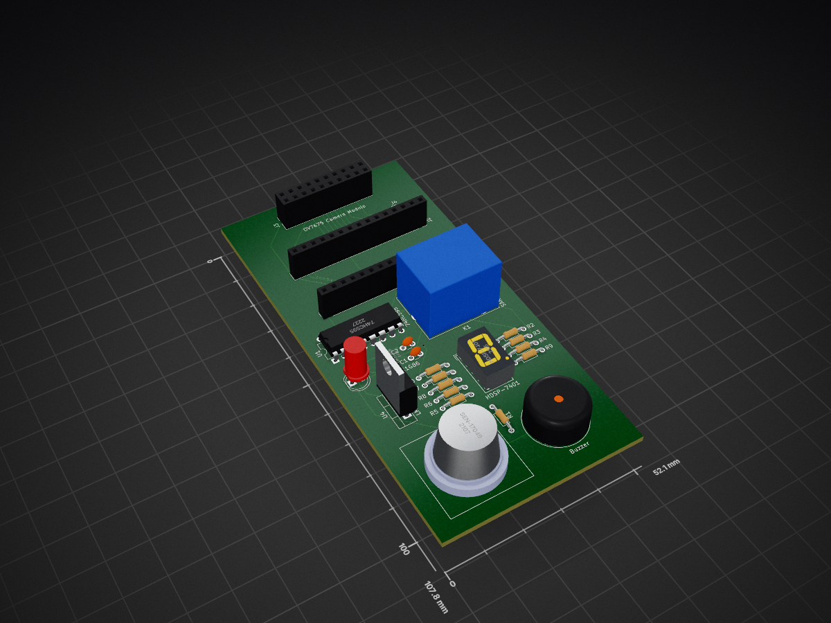
PCB Layout is an open-source printed circuit board by anwaypimpalkar, from the anwaypimpalkar/smartElevatorSystem repository on GitHub. It is a 4-layer board of 52.1 × 107.8 mm with 24 parts on 55 nets, routed with 209 tracks and 2 vias.
It is built around the SEN-17049, 74AHC1G86SE and 74HC595, with the HDSP-7401 among its other parts. Its parts include 10 resistors, 5 ICs, 4 connectors, 2 capacitors and 1 diode. It belongs with the radio and wireless boards and the AVR (ATmega, ATtiny) boards of this library.


April - June 2021 | Micro Project in SY BTech
June 2021: Awarded "Best Project" out of a pool of 1000+ projects at the 5th IEEE National Level Project Competition.
January 2022: Check out the Arduino Team's Blog Post covering this project!
Using an approach of Embedded Machine Learning, we built a multi-tenant architecture to facilitate a contactless elevator system. It consists of two parts – person detection and speech recognition. To create an effective pipeline, we used multiple signal processing techniques to extract necessary features from the input signals. Further, we developed a fire safety system using basic yet functional sensors in two methods – using a microcontroller and using an operational amplifier. These systems are deployed outside and inside an elevator, respectively. Lastly, we built a PCB to house all these components and make a holistically deployable product.
First, we would want a person to come and stand in front of the elevator, indicating that he wants to use it. Then, the person would speak the floor number he would like to visit, and the elevator system recognizes the floor number which was spoken. The elevator then operates as it should and the doors should open for him. The overall flow of the system is shown in the figure below.

The project is a three-part system encompassing the following subsystems:
Person recognition (VWW Detection) and voice recognition (KWS) to operate the elevator.
Fire safety mechanism inside the elevator to drop installed oxygen masks and signal the main elevator interface.
Fire safety and detection system outside the elevator on different floors bundled with the features mentioned in point (1).
A generic block diagram of the entire system is shown below.

The KWS and VWW models are combined in a multi-tenant architecture. In such a structure, only one of the two models runs inference on the input data at a time. This allows for fast inferences and efficient memory allocation when and wherever required. As our development board of choice - Arduino Nano 33 BLE Sense, has limited resources available on board (1MB CPU Flash Memory, 256KB SRAM), the neural network on the system had to be memory and energy efficient compared to a whole scale neural network model. Further post-training quantization methods were implemented to reduce the size of the model (KWS model: 26,720 bytes; VWW model: 3,00,568 bytes; Total size after compilation: 207712 bytes 79% of dynamic memory) and latency of the inferences in real time.
The Visual Wake Word model used for our elevator use case is based on an existing MobileNets model. The core concept behind the architecture is depthwise separable convolution. This is a variant of classical two-dimensional convolutions that works in a much more efficient way, without compromising on accuracy greatly. The model has various steps, as shown in the figure below. Namely, these steps are Initialization, Pre-Processing, Model Inference, and Response.

To enable a completely contactless experience for the elevator interface, we implemented a speech recognition approach to choose the floor number that a given user would like to go to. We went on to implement a KWS (Keyword Spotting) model to satisfy this requirement. The chosen keywords were floor numbers in the lower order “One”, “Two”, “Three” and “Four”. Like the VWW model, the KWS model has 4 high level steps in the system as shown in the figure below. Compared to the prior, this model is relatively lightweight and takes lesser time for training and inference.

To make it easier for the CNN to process and classify the audio signals into different categories, we extract the features of the buffer audio sample before passing it into an inference pipeline. The various steps of feature extraction are:
Due to the memory and power constraints on any embedded microcontroller, running two CNN inference engines simultaneously is a challenge. Our approach to this problem was to implement a multi-tenant architecture for combining the KWS and VWW model. In such a structure, only one of the two models runs inference on the input data at a time. Both models share the TensorArena and use the same memory allocations. This allowed for fast inferences and efficient memory allocation when and wherever required. There is also no requirement for the synchronization of data streams from the camera module and the microphone, both of which are running at different sampling rates.
Elevator shafts may be exposed to smoke and that smoke could reach occupants not just inside the elevator but on other floors as well. In such situations, the elevator is advised to return to the ground floor of the building immediately. The most efficient way to develop a fire safety system which protects the occupants of an elevator is to design a system which works in tandem with it the smoke/flammable gas detectors and temperature sensors directly. To maximize the efficiency of such a system, we developed a pipeline in which the main elevator interface has direct inputs from the smoke detection units. Depending on the levels obtained from the sensors, the elevator interface can further be commanded to execute a specific set of instructions, for example taking the elevator to the lowest floor immediately in the case of a fire.
To implement our approach, we chose to use a MQ-2 Smoke/Flammable Gas Detector and a LM-35 Temperature sensor.
The hardware required for the implementation of the contactless elevator system, i.e., the VWW and KWS models was readily available with us, namely the Arduino Nano 33 BLE Sense and OV7675 Camera Module. They are mounted on a shield for the scope of this experiment. Further into the implementation, we designed our own shield to house the OV7675 and Arduino module along with other peripherals.
Once the shield was properly positioned, we ran inference by standing inside and outside the frame of the camera. As discussed in the System Architecture chapter, each inference returns a probability value between -127 and +127, where higher numbers indicate a higher probability of a human subject being present in the frame.
The camera input of greyscale QCIF images of size 144 x 176 pixels with human subject are shown below.

Once the inference engine is run, the probability values are generated. These values are printed on the serial monitor of the Arduino IDE. When a person is entering the frame or in motion, the camera is unable to pick up the fast movement due to the low frame rate. At such moments, the model is decisive of whether a person is the frame or not. Hence, while classifying as a human detected in the field of view, we chose to keep a minimum Person score of 25. This threshold value reduces the number of false positives. If a person is detected in the frame, the green RGB light on the Arduino is lit up, whereas when there is no person detected, the red RGB light is lit up.
Once a person has been detected in the frame, the KWS model inference engine is triggered, and the system starts listening for keywords spoken by the user to communicate the floor number which they would like to go to. These numbers are chosen to be “One”, “Two”, “Three”, and “Four”. The incoming audio is sampled at 16 kHz and ran inference on every one second. Whenever the Arduino is listening for a keyword, the yellow light rapidly blinks, and upon positive inference, the blue RGB light is lit up. The different LED states are shown in the image below.

The fire safety system outside the elevator bundled with the deployed unit was simulated on Proteus. The system consisted of the following components:
Since the Arduino Nano 33 BLE Sense was not available as a library for simulation, we used the Arduino Nano baseline model for it. The architecture is similar and hence is adequate for the purposes of the project. For the sake of completeness in the project, we chose to go create a pseudo-main elevator interface using an Arduino Uno in the simulation. A 4 x 16 LCD Display was also added for us to keep track of the system status. The figure below shows the circuit schematic for the project on Proteus. The Arduino Nano is interfaced with a LM-35 and MQ-2 sensor, a 7 Segment Display and an alarm system which is triggered when the system is simulating a fire scenario.

To house the components of this project, we created a Printed Circuit Board design using KiCAD, an open-source EDA software. Some key specifications of the PCB are:
The PCB consists of 4 Copper layers.
Front and Back Copper Layers are signal layers.
Inner1 Copper layer contains a Power Plane.
Inner2 Copper layer contains a Ground Plane.
All components used utilize Through Hole Technology (THT) except for 74AHC1G86 Dual Input Single Output EX-OR Gate which uses SMT.

The hardware required was implemented as a proof of concept for the evaluation of the project. An unnarrated video demonstration has been documented.
| Qty | Value | Footprint | References |
|---|---|---|---|
| 8 | 330Ω | Resistor_THT:R_Axial_DIN0204_L3.6mm_D1.6mm_P7.62mm_Horizontal | R2, R3, R4, R5, R6, R7, R8, R9 |
| 1 | 10uF | Capacitor_THT:C_Disc_D3.0mm_W1.6mm_P2.50mm | C1 |
| 1 | 1uF | Capacitor_THT:C_Disc_D3.0mm_W1.6mm_P2.50mm | C2 |
| 1 | 4kΩ | Resistor_THT:R_Axial_DIN0204_L3.6mm_D1.6mm_P7.62mm_Horizontal | R1 |
| 1 | 74AHC1G86 | Package_TO_SOT_SMD:SOT-23-5 | U5 |
| 1 | 74HC595 | Package_DIP:DIP-16_W7.62mm | U1 |
| 1 | 75Ω | Resistor_THT:R_Axial_DIN0204_L3.6mm_D1.6mm_P7.62mm_Horizontal | R10 |
| 1 | Buzzer | Buzzer_Beeper:Buzzer_15x7.5RM7.6 | BZ1 |
| 1 | HDSP-7401 | Display_7Segment:HDSP-7401 | U2 |
| 1 | L Arduino Mount | Connector_PinSocket_2.54mm:PinSocket_1x15_P2.54mm_Vertical | J1 |
| 1 | LED | LED_THT:LED_D5.0mm_FlatTop | D1 |
| 1 | LM35-NEB | Package_TO_SOT_THT:TO-220-3_Vertical | U4 |
| 1 | OV7675 Camera Module | Connector_PinSocket_2.54mm:PinSocket_2x10_P2.54mm_Vertical | J3 |
| 1 | R Arduino Mount | Connector_PinSocket_2.54mm:PinSocket_1x15_P2.54mm_Vertical | J2 |
| 1 | SANYOU_SRD_Form_C | Relay_THT:Relay_SPDT_SANYOU_SRD_Series_Form_C | K1 |
| 1 | SEN-17049 | SEN-17049:SEN17049 | U3 |
| 1 | To Main Elevator System | Connector_PinHeader_2.54mm:PinHeader_1x01_P2.54mm_Vertical | J4 |
camerongrimes/gdip-test-tube-hardware
Hardware for GDIP test tube robot

Diinidu12/Simple_Seven_segment_Counter
This is a simple PCB designing project for follow the all the professional steps and build a quality and manufacturable PCB

Ishan-tron/Digital_Clock_PCB
PCB version of | Diy 7 Segment Digital Clock With ATmega328P Chip | https://www.youtube.com/watch?v=LZik-IQQH7Q


nirav1385/BCD-counter-using-D_flipflop
BCD Counter (0-9) using D-Flip Flops (74LS74) — Complete KiCad project with schematic, PCB layout, Gerber files & 3D renders. Built with NE555 + 74LS74 + 74LS00 + 74LS47 + 7-Segment Display.


muhammadsyafrieagunghandaya-dotcom/MyPCB
This repository contains my collection of PCB design works created using KiCad and other tools. Most of these projects are part of my learning process in electronics, along with some experiments and personal ideas.

It measures 52.1 × 107.8 mm and has 4 copper layers, 1.6 mm thick.
24 parts, built around the SEN-17049, 74AHC1G86SE, 74HC595 and HDSP-7401. The full list of its parts is on this page, with links to each part's symbol and footprint where PCBKit's library has them.
From the anwaypimpalkar/smartElevatorSystem repository on GitHub, at the commit this page was made from: the board is KiCAD PCB Design/PCB Layout/PCB Layout.kicad_pcb. PCBKit opens the board in the browser, with nothing to install.
Its repository states no licence, so its author keeps all rights: ask anwaypimpalkar before reusing the design.