2 layers48.5 × 45 mm
Seven segment counter Circuit
Diinidu12/Simple_Seven_segment_Counter
This is a simple PCB designing project for follow the all the professional steps and build a quality and manufacturable PCB
15 partsApache-2.0

 nirav1385/BCD-counter-using-D_flipflop
BCD Counter (0-9) using D-Flip Flops (74LS74) — Complete KiCad project with schematic, PCB layout, Gerber files & 3D renders. Built with NE555 + 74LS74 + 74LS00 + 74LS47 + 7-Segment Display.
Bcd counter using d flipfflop is an open-source printed circuit board by nirav1385, from the nirav1385/BCD-counter-using-D_flipflop repository on GitHub. It is a 2-layer board of 136.3 × 43.8 mm with 24 parts on 33 nets, routed with 245 tracks and 0 vias.
It is built around the 74LS74PC, 74LS00SC and HDSP-7401, with the NE555P among its other parts. Its parts include 9 resistors, 6 ICs, 2 capacitors and 1 connector.


A complete BCD (Binary-Coded Decimal) Counter built from scratch using D-type Flip-Flops (74LS74), designed and routed in KiCad 10.0. This project demonstrates synchronous digital counter design using discrete TTL logic ICs with a 7-segment display output.
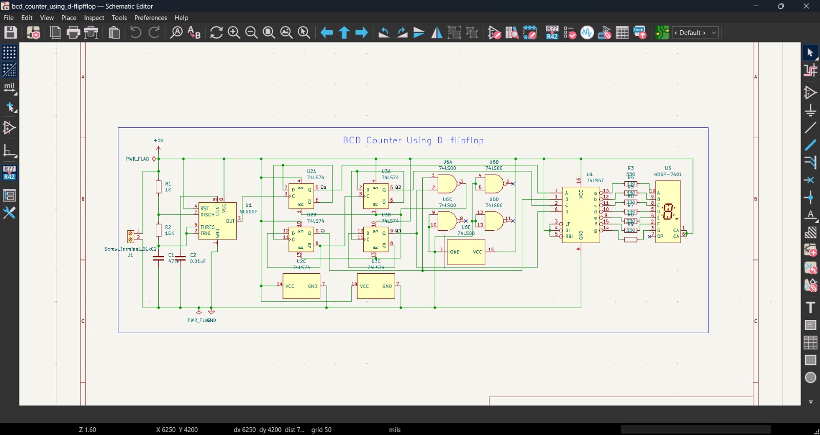
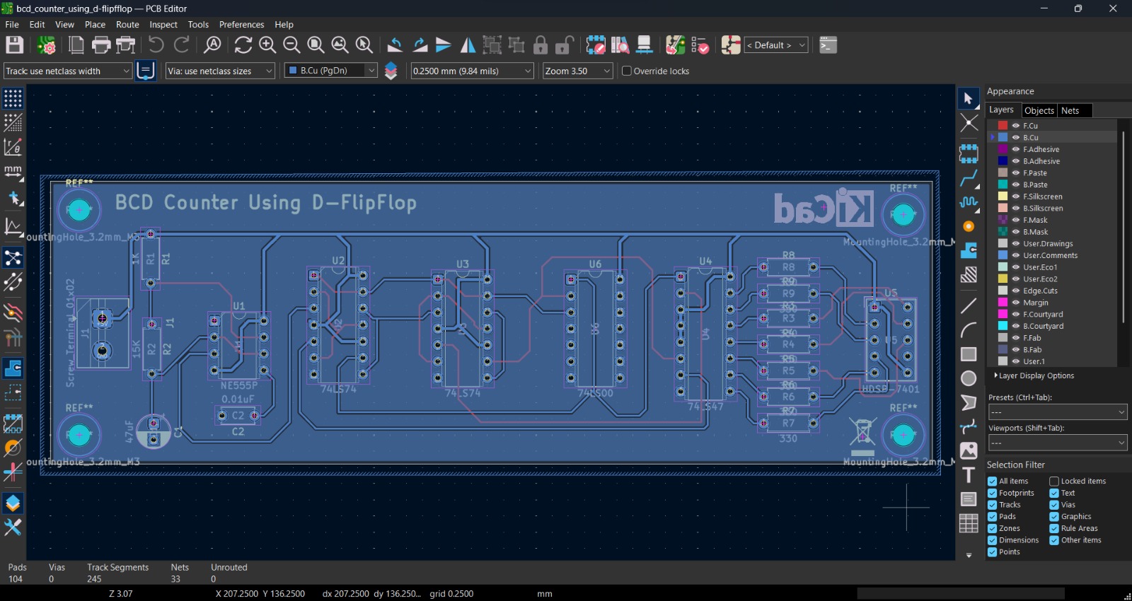
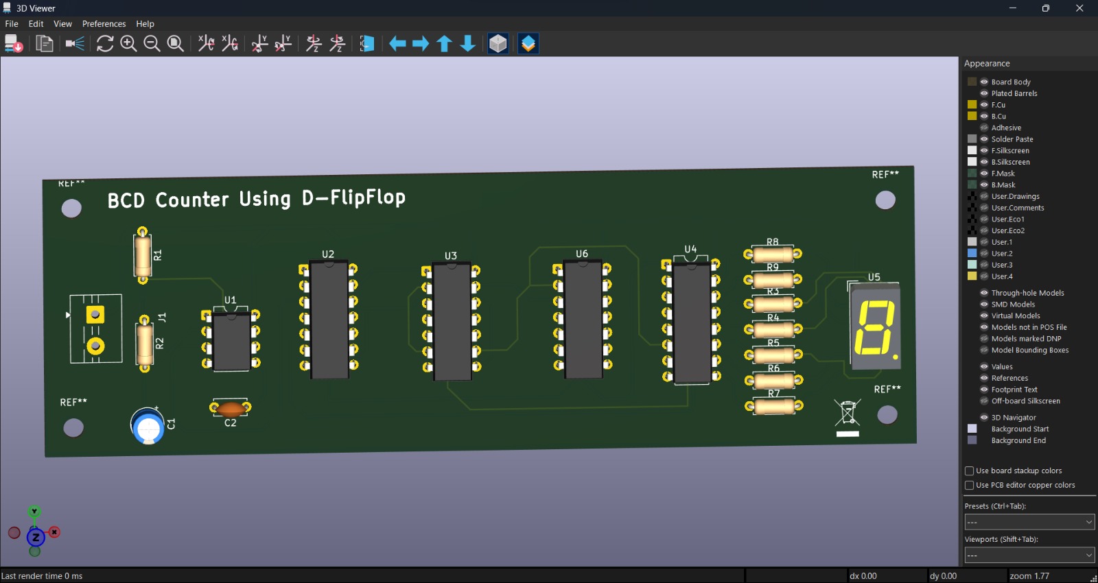
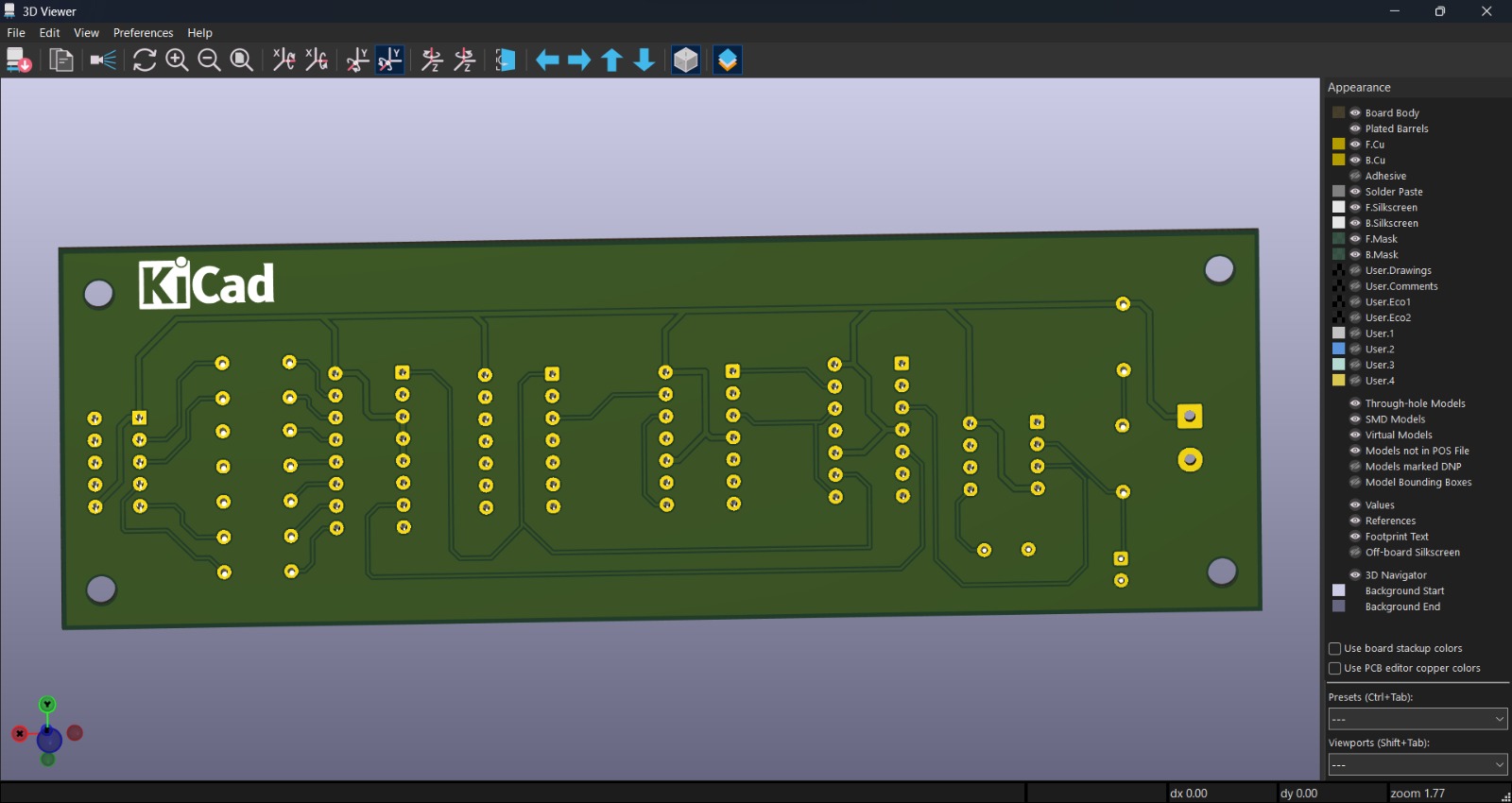
A BCD counter counts from 0 to 9 (binary 0000 to 1001) and then resets back to 0. This design achieves that using:
10 (binary 1010) and force a reset, ensuring the counter wraps around after 9.| Decimal | Q3 | Q2 | Q1 | Q0 |
|---|---|---|---|---|
| 0 | 0 | 0 | 0 | 0 |
| 1 | 0 | 0 | 0 | 1 |
| 2 | 0 | 0 | 1 | 0 |
| 3 | 0 | 0 | 1 | 1 |
| 4 | 0 | 1 | 0 | 0 |
| 5 | 0 | 1 | 0 | 1 |
| 6 | 0 | 1 | 1 | 0 |
| 7 | 0 | 1 | 1 | 1 |
| 8 | 1 | 0 | 0 | 0 |
| 9 | 1 | 0 | 0 | 1 |
| Reset | 1 | 0 | 1 | 0 |
After reaching
9, the NAND gate logic detects1010(Q3·Q1) and resets all flip-flops to0000.
| Ref | Component | Value / Part No. | Quantity | Description |
|---|---|---|---|---|
| U1 | NE555P | NE555P | 1 | Timer IC — Clock generator (Astable) |
| U2, U3 | 74LS74 | 74LS74 | 2 | Dual D-Type Flip-Flop (4 flip-flops) |
| U4 | 74LS47 | 74LS47 | 1 | BCD-to-7-Segment Decoder/Driver |
| U5 | HDSP-7401 | HDSP-7401 | 1 | Common-Anode 7-Segment Display |
| U6 | 74LS00 | 74LS00 | 1 | Quad 2-Input NAND Gate (reset logic) |
| R1 | Resistor | 1KΩ | 1 | NE555 timing resistor |
| R2 | Resistor | 15KΩ | 1 | NE555 timing resistor |
| R3–R9 | Resistor | 330Ω | 7 | Current-limiting resistors for display |
| C1 | Electrolytic Capacitor | 47µF | 1 | NE555 timing capacitor |
| C2 | Ceramic Capacitor | 0.01µF | 1 | NE555 decoupling/noise filter capacitor |
| J1 | Screw Terminal | 01×02 | 1 | Power input connector (+5V / GND) |
Total ICs: 6 | Total Passives: 11 | Total Components: 18
| Parameter | Value |
|---|---|
| Supply Voltage | +5V DC |
| Input Connector | Screw Terminal (J1) |
| Logic Family | 74LS (TTL) |
⚠️ Do NOT exceed 5.25V as the 74LS series TTL ICs have a maximum operating voltage of 5.25V.
The NE555 is configured in Astable (free-running) mode to generate a continuous square wave clock signal.
f = 1.44 / ((R1 + 2×R2) × C1)
f = 1.44 / ((1000 + 2×15000) × 0.000047)
f ≈ 0.99 Hz  (~1 count per second)
The counter advances approximately once per second, making the count changes easily visible on the 7-segment display.
bcd_counter_using_d-flipfflop/
│
├── 📄 README.md                                    ← You are here
├── 📐 bcd_counter_using_d-flipfflop.kicad_sch      ← Schematic file
├── 🟢 bcd_counter_using_d-flipfflop.kicad_pcb      ← PCB layout file
├── ⚙️ bcd_counter_using_d-flipfflop.kicad_pro      ← KiCad project file
│
├── 📁 images/
│   ├── 🖼️ schematic_diagram.jpeg                   ← Circuit schematic screenshot
│   ├── 🖼️ pcb_layout.jpeg                          ← PCB layout screenshot
│   ├── 🖼️ 3d_view_front.jpeg                       ← 3D render (front side)
│   └── 🖼️ 3d_view_back.jpeg                        ← 3D render (back side)
│
└── 📁 Gerber/
    ├── bcd_counter_using_d-flipfflop-F_Cu.gbr       ← Front copper layer
    ├── bcd_counter_using_d-flipfflop-B_Cu.gbr       ← Back copper layer
    ├── bcd_counter_using_d-flipfflop-F_Mask.gbr     ← Front solder mask
    ├── bcd_counter_using_d-flipfflop-B_Mask.gbr     ← Back solder mask
    ├── bcd_counter_using_d-flipfflop-F_Paste.gbr    ← Front solder paste
    ├── bcd_counter_using_d-flipfflop-B_Paste.gbr    ← Back solder paste
    ├── bcd_counter_using_d-flipfflop-F_Silkscreen.gbr ← Front silkscreen
    ├── bcd_counter_using_d-flipfflop-B_Silkscreen.gbr ← Back silkscreen
    ├── bcd_counter_using_d-flipfflop-Edge_Cuts.gbr  ← Board outline
    ├── bcd_counter_using_d-flipfflop-PTH.drl        ← Plated through-holes
    ├── bcd_counter_using_d-flipfflop-NPTH.drl       ← Non-plated holes
└── bcd_counter_using_d-flipfflop-job.gbrjob ← Gerber job file| Parameter | Value |
|---|---|
| PCB Layers | 2 (Front & Back Copper) |
| Track Width | 0.25mm (9.84 mils) |
| Total Pads | 104 |
| Total Vias | 0 |
| Track Segments | 245 |
| Total Nets | 33 |
| Unrouted Nets | 0 ✅ |
| Mounting Holes | 4× M3 (3.2mm) |
| Design Tool | KiCad 10.0 |
✅ All nets are fully routed — The PCB design is complete with zero unrouted connections.
File → Open Projectbcd_counter_using_d-flipfflop.kicad_proGerber/ folder contains all manufacturing filesGerber/ folder to any PCB manufacturer:
A D-Flip Flop can be used as a toggle flip-flop by connecting its Q̅ (complementary) output back to the D input. On each rising edge of the clock, it toggles its state — this is the fundamental building block for binary counters.
A standard 4-bit binary counter counts from 0000 to 1111 (0–15). A BCD counter is modified to count only from 0000 to 1001 (0–9) by adding reset logic that detects the invalid state 1010 (decimal 10) and immediately resets all flip-flops to 0000.
The NAND gates monitor Q3 and Q1. When both are HIGH (indicating count = 10 in binary, 1010), the NAND gate output goes LOW, which asynchronously clears (resets) all flip-flops back to 0000.
This project is open-source. Feel free to use, modify, and share it for educational purposes.
Nirav Jain - Designed and developed as an electronics/digital logic project using KiCad EDA.
⭐ If you found this project helpful, give it a star! ⭐
| Qty | Value | Footprint | References |
|---|---|---|---|
| 7 | 330 | Resistor_THT:R_Axial_DIN0207_L6.3mm_D2.5mm_P7.62mm_Horizontal | R3, R4, R5, R6, R7, R8, R9 |
| 2 | 74LS74 | Package_DIP:DIP-14_W7.62mm | U2, U3 |
| 1 | 0.01uF | Capacitor_THT:C_Disc_D5.0mm_W2.5mm_P5.00mm | C2 |
| 1 | 15K | Resistor_THT:R_Axial_DIN0207_L6.3mm_D2.5mm_P7.62mm_Horizontal | R2 |
| 1 | 1K | Resistor_THT:R_Axial_DIN0207_L6.3mm_D2.5mm_P7.62mm_Horizontal | R1 |
| 1 | 47uF | Capacitor_THT:CP_Radial_D5.0mm_P2.50mm | C1 |
| 1 | 74LS00 | Package_DIP:DIP-14_W7.62mm | U6 |
| 1 | 74LS47 | Package_DIP:DIP-16_W7.62mm | U4 |
| 1 | HDSP-7401 | Display_7Segment:HDSP-7401 | U5 |
| 1 | NE555P | Package_DIP:DIP-8_W7.62mm | U1 |
| 1 | Screw_Terminal_01x02 | TerminalBlock:TerminalBlock_MaiXu_MX126-5.0-02P_1x02_P5.00mm | J1 |
The 18 most common of 24 parts.
Diinidu12/Simple_Seven_segment_Counter
This is a simple PCB designing project for follow the all the professional steps and build a quality and manufacturable PCB

fortinsylvain/MyCpu
Home brew CPU Hardware with 1-bit ALU implementation using 74LSxx, a micro-code and assembler coded in C#.

TomNisbet/sap-plus
Simple As Possible (SAP) 8-bit computer with a modular PCB design


flypie/Ace-2019
Reimplimentation of the Jupiter ACE with slightly more modern hardware. https://www.jupiter-ace.co.uk/ the KiCad versions are the up to date designs which are available at https://jupiterdeuce.blogspot.com and…

brandtdamman/i281e-cpu
Developed by SDMAY24-14 Senior Design group under Dr. Stoytchev, the i281e CPU is an extended design from the original i281 CPU for educational purposes.
It measures 136.3 × 43.8 mm and has 2 copper layers, 1.6 mm thick.
24 parts, built around the 74LS74PC, 74LS00SC, HDSP-7401 and NE555P. The full list of its parts is on this page, with links to each part's symbol and footprint where PCBKit's library has them.
From the nirav1385/BCD-counter-using-D_flipflop repository on GitHub, at the commit this page was made from: the board is bcd_counter_using_d-flipfflop.kicad_pcb and its schematic bcd_counter_using_d-flipfflop.kicad_sch. PCBKit opens the board in the browser, with nothing to install.
Its repository states no licence, so its author keeps all rights: ask nirav1385 before reusing the design.