2 layers11.8 × 14.6 mm
 idlehandsdev/fanFDD
The firmware and CAD for the neural network fan fault detector.
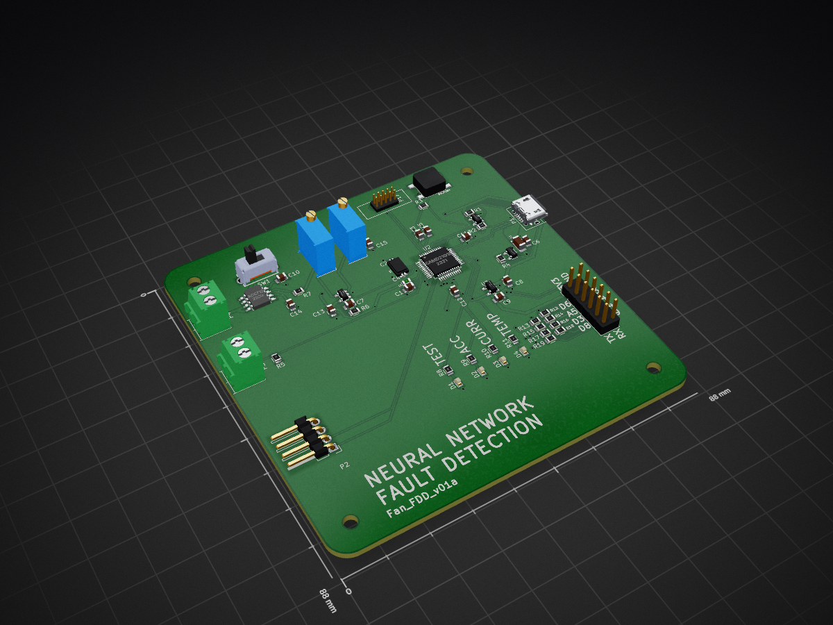
FanFDD is an open-source printed circuit board by idlehandsdev, from the idlehandsdev/fanFDD repository on GitHub. It is a 2-layer board of 88 × 88 mm with 57 parts on 72 nets, routed with 561 tracks and 62 vias.
It is built around the 74AHC1G125GW and OPA344PA. Its parts include 19 resistors, 15 capacitors, 6 connectors, 5 ICs and 4 diodes. It belongs with the SAM D and SAM boards of this library.


A Neural network robot for learning new sensors without programming them specifically.
| Qty | Value | Footprint | References |
|---|---|---|---|
| 14 | 1k | Resistors_SMD:R_0805 | R5, R7, R8, R9, R10, R11, R12, R13, R14, R15, R16, R17, R18, R19 |
| 8 | 0.1uF | Capacitors_SMD:C_0805 | C1, C3, C5, C10, C11, C12, C13, C15 |
| 4 | LED | LEDs:LED-0603 | D1, D2, D3, D4 |
| 2 | 15pF | project_footprints:C_0402_Hand | C2, C4 |
| 2 | 2.2uF | Capacitors_SMD:C_0805 | C6, C9 |
| 2 | POT | Potentiometers:Potentiometer_Bourns_3296W_3-8Zoll_Inline_ScrewUp | RV1, RV2 |
| 1 | 1000pF | Capacitors_SMD:C_0805 | C14 |
| 1 | 100k | Resistors_SMD:R_0805 | R1 |
| 1 | 100pF | Capacitors_SMD:C_0805 | C7 |
| 1 | 10k | Resistors_SMD:R_0805 | R3 |
| 1 | 1uF | Capacitors_SMD:C_0805 | C8 |
| 1 | 330 | Resistors_SMD:R_0805 | R2 |
| 1 | 47K | Resistors_SMD:R_0805 | R4 |
| 1 | 47k | Resistors_SMD:R_0805 | R6 |
| 1 | 500mA | project_footprints:c_1206 | F1 |
| 1 | 74AHC1G125 | project_footprints:sot23-5 | U1 |
| 1 | ACS712 | SMD_Packages:SOIC-8-N | U4 |
| 1 | AP2112K-3.3V | TO_SOT_Packages_SMD:SOT-23-5 | U3 |
| 1 | CONN_01X04 | Pin_Headers:Pin_Header_Angled_1x04 | P2 |
| 1 | CONN_02X06 | Pin_Headers:Pin_Header_Straight_2x06_Pitch2.54mm | P5 |
| 1 | Crystal_Small | idlehands_footprints:crystal_smd_3.20x1.50mm2 | Y1 |
| 1 | DBG_CONN | idlehands_footprints:Atmel_ICE_Connector_02x05 | P17 |
| 1 | FB - 30Ohm | project_footprints:R_SM0603 | L1 |
| 1 | MOTOR | Terminal_Blocks:TerminalBlock_Pheonix_PT-3.5mm_2pol | P4 |
| 1 | MOTOR_SW | idlehands_footprints:OS102011MS2QN1 Slide Switch | SW1 |
| 1 | OPA344 | idlehands_footprints:sot23-5 | U5 |
| 1 | Q_PMOS_DSG | idlehands_footprints:DMG2307L | Q1 |
| 1 | SAMD21G18 | project_footprints:TQFP-48_7x7mm_Pitch0.5mm | U2 |
| 1 | SW_PUSH | idlehands_footprints:PTS-LFS | SW4 |
| 1 | THERM | Terminal_Blocks:TerminalBlock_Pheonix_PT-3.5mm_2pol | P3 |
| 1 | USB_OTG | Connect:USB_Micro-B | P1 |
It measures 88 × 88 mm and has 2 copper layers, 1.6 mm thick.
57 parts, built around the 74AHC1G125GW and OPA344PA. The full list of its parts is on this page, with links to each part's symbol and footprint where PCBKit's library has them.
From the idlehandsdev/fanFDD repository on GitHub, at the commit this page was made from: the board is PCB/fanfdd.kicad_pcb. PCBKit opens the board in the browser, with nothing to install.
Its repository states no licence, so its author keeps all rights: ask idlehandsdev before reusing the design.

Poppy-Robotics/rtk
CAN enabled, RTK GNSS module for robotics based on u-blox ZED-X20P

SolderedElectronics/Current-sensor-30A-ACS712-breakout-hardware-design
Hardware design, BOM, gerbers and 3D files for Current-sensor-30A-ACS712-breakout designed by Soldered Electronics.


CRImier/MyKiCad
My KiCad boards. Can't be bothered uploading individually anymore, so here you go.


jsphuebner/inverter-hardware
Eagle schematics of inverter main board, sensor boards and gate drivers
