2 layers17 × 12 mm
 ibScale/ibScaleSeqRails
Sequential feeder rails with power protection for the LumenPNP
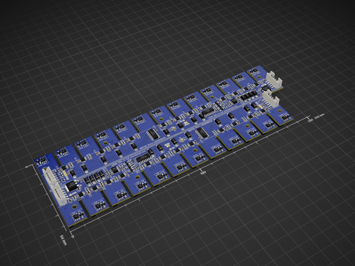
IbScaleSeqRails is an open-source printed circuit board by ibScale, from the ibScale/ibScaleSeqRails repository on GitHub, published under the CERN-OHL-S-2.0 licence. It is a 4-layer board of 203 × 64 mm with 305 parts on 373 nets, routed with 2,374 tracks and 346 vias.
It is built around the DS28E07P+T, 74HC595 and LM78M05CH, with the NE555D and SS34 among its other parts. Its parts include 72 resistors, 58 ICs, 52 diodes, 45 capacitors and 29 connectors.


Enhanced feeder rails for the Opulo LumenPNP. Provides power-up sequencing and port protection. These are desgined to be a drop-in replacement for the stock rails.
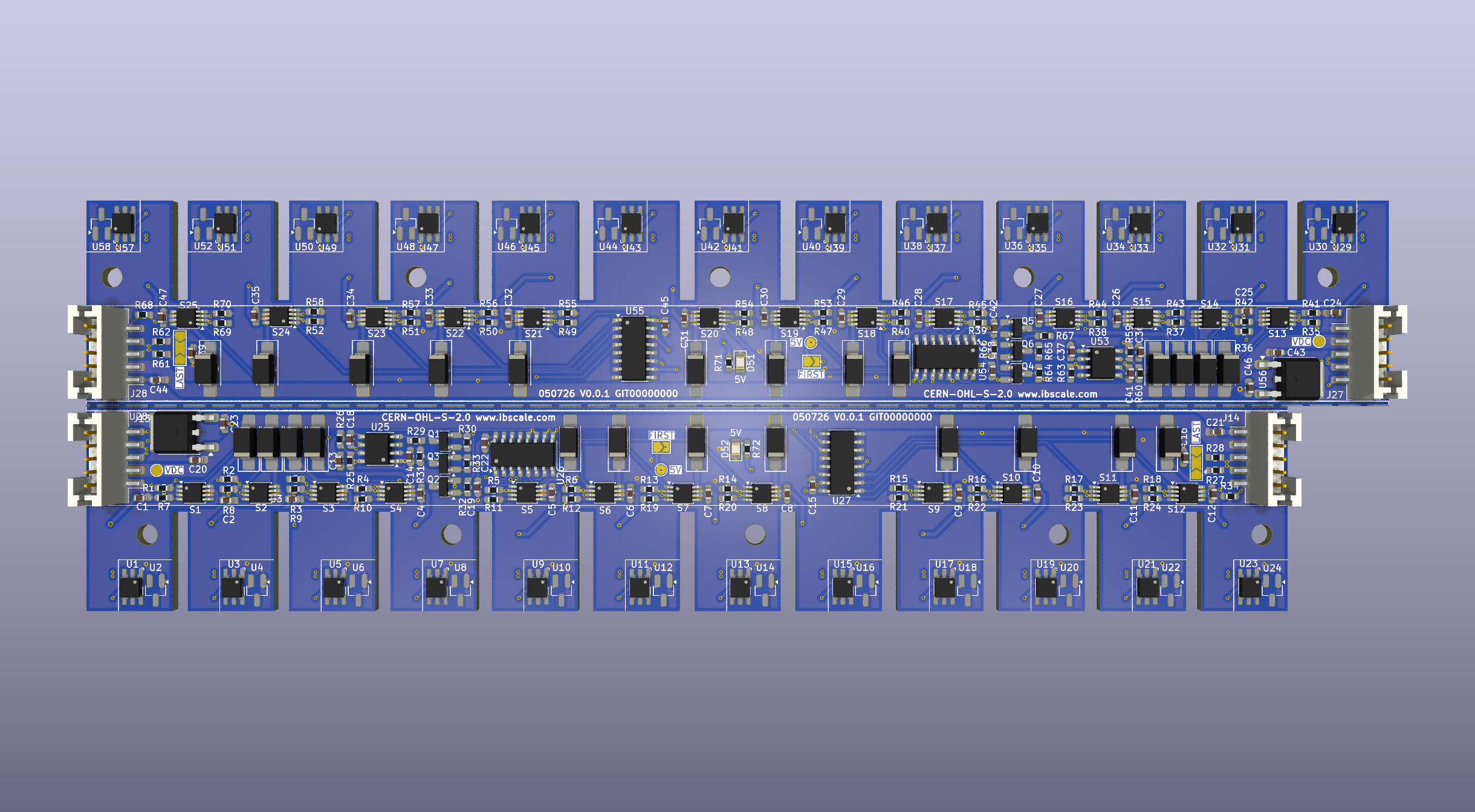 Front side of the 2-up panel: the 13-port blade (top) and 12-port blade (bottom), joined by a V-Cut.
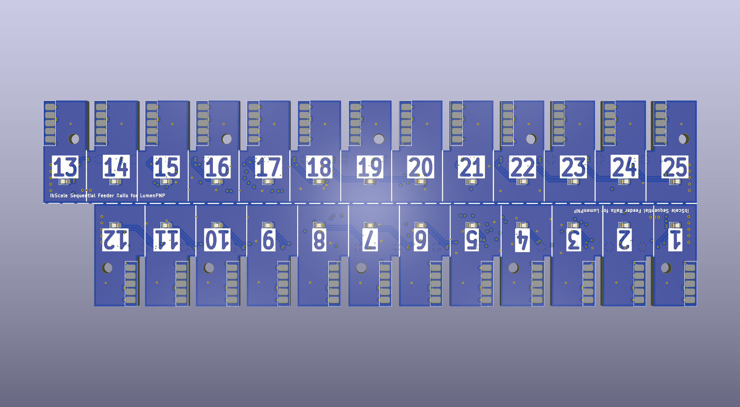 Back side, showing per-port slot numbers and the optional LED fault indicator
A fully loaded LumenPNP can have 50 feeders connected to the 24V feeder bus, each with its own 100uF input capacitor. When the machine powers up, every feeder starts charging its input capacitors at the same time. This massive capacitive load can sag (brown-out) the 24V bus or trip the power supply's over-current protection, causing the machine to restart or fail to power on.
The stock feeder rails also have no power protection on the exposed 24V surface contacts that feeders plug into. A dropped screw, a loose SMD part, or a faulty feeder motherboard can pull down the entire 24V bus and take out every feeder and possibly the machine at once.
Each rail sequentially enables its feeder ports roughly 75ms apart, so feeders power up one at a time instead of all at once. Every port is individually current-limited and short-circuit protected, so a fault on one feeder doesn't affect the others on the shared bus.
The stock LumenPNP feeder rail connector is a 4-pin JST-PH (24V, GND, RS-485 A/B). To pass the sequencing hand-off signal from rail to rail, the IN/OUT connectors on this board use a 5-pin JST-PH instead — the extra pin carries the sequencing trigger alongside the pass-through power and RS-485 comms.
Because the LumenPNP wiring harness only uses a 4-pin housing you'll have to:
You will also need new 5-pin JST-PH cables to connect the rails together. These are relatively easy to order pre-made and inexpensive.
Every feeder slot is switched through a TI TPS1H000A smart high-side switch, giving each port independent:
A fault at one feeder's surface contacts (loose debris, a shorted or bad feeder motherboard, etc.) trips only that port, instead of browning out or shutting down the entire 24V bus. During a detectable fault condition the port's optional fault indicator LED will turn on.
This is a KiCad 10 project. The design is panelized as a 2-up panel with a V-Cut (the User.1 layer) down the middle:
blade-12.kicad_sch — a self-contained 12-port sequencer rail (its own 555, shift registers, IN/OUT connectors, and FIRST/LAST jumpers).blade-13.kicad_sch — a self-contained 13-port sequencer rail, identical in function.The panel is v-scored during production and simply needs to be snapped along the V-Cut line. This gives you a complete rail set for one side of the machine.
The project also defines a BackRails variant. This variant renumbers/relabels the silkscreen slot numbers for rails to be mounted on the rear of the machine, so front and rear rail slot numbering stays consistent without needing a permanent marker.
Each feeder slot also carries a DS28E07 1-Wire EEPROM, one per port, for slot/feeder identification. A second footprint for an AT21CS01 EEPROM has also been added for future feeder firmware updates that might support alternative EEPROM types.
RS485 network termination is improved with two 60-ohm resistors in series with a 100nf cap from the center to ground. This provides increased common-mode rejection and improved signal integrity.
There is an unpopulated LED on the back side of the board for an optional fault indicator. Any standard 0805 5V tolerant LED will work. There is a 810-ohm current limiting resistor already installed in series with the LED.
ibScaleSeqRails.kicad_pro     Project file
ibScaleSeqRails.kicad_sch     Top-level schematic (instantiates both blades)
ibScaleSeqRails.kicad_pcb     PCB layout (2-up panel, V-Cut on User.1)
blade-12.kicad_sch            12-port rail sub-schematic
blade-13.kicad_sch            13-port rail sub-schematic
library/ Local symbols, footprints, and 3D modelsBill of materials
PCB specification
Mounting holes
Released under CERN-OHL-S-2.0. See LICENSE.txt for full terms.
Designed for the Opulo LumenPNP feeder rail system. Not affiliated with or endorsed by Opulo.
| Qty | Value | Footprint | References |
|---|---|---|---|
| 50 | 470r | Resistor_SMD:R_0603_1608Metric_Pad0.98x0.95mm_HandSolder | R1, R2, R10, R11, R12, R13, R14, R15, R16, R17, R18, R19, R20, R21, R22, R23 +34 |
| 35 | 100n | Capacitor_SMD:C_0603_1608Metric_Pad1.08x0.95mm_HandSolder | C1, C2, C10, C11, C12, C13, C15, C16, C21, C22, C24, C25, C26, C27, C28, C29 +19 |
| 25 | AT21CS01 | Package_TO_SOT_SMD:SOT-23_Handsoldering | U2, U4, U10, U12, U14, U16, U18, U20, U22, U24, U30, U32, U34, U36, U38, U40 +9 |
| 25 | DS28E07P | ibScale:DS28E07_MULTI | U1, U3, U11, U13, U15, U17, U19, U21, U23, U29, U31, U33, U35, U37, U39, U41 +9 |
| 25 | SS34 | Diode_SMD:D_SMA_Handsoldering | D10, D11, D12, D19, D20, D21, D22, D23, D24, D31, D32, D33, D34, D35, D36, D43 +9 |
| 25 | TPS1H000A | Package_SO:MSOP-8-1EP_3x3mm_P0.65mm_EP1.95x2.15mm_ThermalVias | S1, S2, S10, S11, S12, S13, S14, S15, S16, S17, S18, S19, S20, S21, S22, S23 +9 |
| 10 | MountingHole | MountingHole:MountingHole_3.2mm_M3 | H1, H2, H3, H4, H5, H6, H7, H8, H9, H10 |
| 8 | 10k | Resistor_SMD:R_0603_1608Metric_Pad0.98x0.95mm_HandSolder | R26, R31, R32, R33, R60, R65, R66, R67 |
| 8 | 2.2k | Resistor_SMD:R_0603_1608Metric_Pad0.98x0.95mm_HandSolder | R25, R29, R30, R34, R59, R63, R64, R68 |
| 4 | 1u | Capacitor_SMD:C_0603_1608Metric_Pad1.08x0.95mm_HandSolder | C20, C23, C43, C46 |
| 4 | 2N7002 | Package_TO_SOT_SMD:SOT-23_Handsoldering | Q1, Q2, Q4, Q5 |
| 4 | 4.7u | Capacitor_SMD:C_0603_1608Metric_Pad1.08x0.95mm_HandSolder | C14, C19, C37, C42 |
| 4 | 60.4r | Resistor_SMD:R_0603_1608Metric_Pad0.98x0.95mm_HandSolder | R27, R28, R61, R62 |
| 4 | 74HC595 | Package_SO:SOIC-16_3.9x9.9mm_P1.27mm | U26, U27, U54, U55 |
| 2 | 10n | Capacitor_SMD:C_0603_1608Metric_Pad1.08x0.95mm_HandSolder | C18, C41 |
| 2 | 5V | LED_SMD:LED_0805_2012Metric_Pad1.15x1.40mm_HandSolder | D51, D52 |
| 2 | 5V | TestPoint:TestPoint_Pad_D1.5mm | TP1, TP2 |
| 2 | 820r | Resistor_SMD:R_0603_1608Metric_Pad0.98x0.95mm_HandSolder | R71, R72 |
| 2 | DMP68D | Package_TO_SOT_SMD:SOT-23_Handsoldering | Q3, Q6 |
| 2 | FIRST | Jumper:SolderJumper-2_P1.3mm_Open_TrianglePad1.0x1.5mm | JP2, JP4 |
| 2 | IN | Connector_JST:JST_PH_B5B-PH-SM4-TB_1x05-1MP_P2.00mm_Vertical | J13, J27 |
| 2 | LAST | Jumper:SolderJumper-3_P2.0mm_Open_TrianglePad1.0x1.5mm | JP1, JP3 |
| 2 | LM78M05 | Package_TO_SOT_SMD:TO-252-2 | U28, U56 |
| 2 | NE555D | Package_SO:SOIC-8_3.9x4.9mm_P1.27mm | U25, U53 |
| 2 | OUT | Connector_JST:JST_PH_B5B-PH-SM4-TB_1x05-1MP_P2.00mm_Vertical | J14, J28 |
| 2 | VDC | TestPoint:TestPoint_Pad_D1.5mm | TP3, TP4 |
| 1 | 1 | LED_SMD:LED_0805_2012Metric_Pad1.15x1.40mm_HandSolder | D1 |
| 1 | 10 | LED_SMD:LED_0805_2012Metric_Pad1.15x1.40mm_HandSolder | D16 |
| 1 | 11 | LED_SMD:LED_0805_2012Metric_Pad1.15x1.40mm_HandSolder | D17 |
| 1 | 12 | LED_SMD:LED_0805_2012Metric_Pad1.15x1.40mm_HandSolder | D18 |
| 1 | 13 | LED_SMD:LED_0805_2012Metric_Pad1.15x1.40mm_HandSolder | D25 |
| 1 | 14 | LED_SMD:LED_0805_2012Metric_Pad1.15x1.40mm_HandSolder | D26 |
| 1 | 15 | LED_SMD:LED_0805_2012Metric_Pad1.15x1.40mm_HandSolder | D27 |
| 1 | 16 | LED_SMD:LED_0805_2012Metric_Pad1.15x1.40mm_HandSolder | D28 |
| 1 | 17 | LED_SMD:LED_0805_2012Metric_Pad1.15x1.40mm_HandSolder | D29 |
| 1 | 18 | LED_SMD:LED_0805_2012Metric_Pad1.15x1.40mm_HandSolder | D30 |
| 1 | 19 | LED_SMD:LED_0805_2012Metric_Pad1.15x1.40mm_HandSolder | D37 |
| 1 | 2 | LED_SMD:LED_0805_2012Metric_Pad1.15x1.40mm_HandSolder | D2 |
| 1 | 20 | LED_SMD:LED_0805_2012Metric_Pad1.15x1.40mm_HandSolder | D38 |
| 1 | 21 | LED_SMD:LED_0805_2012Metric_Pad1.15x1.40mm_HandSolder | D39 |
| 1 | 22 | LED_SMD:LED_0805_2012Metric_Pad1.15x1.40mm_HandSolder | D40 |
| 1 | 23 | LED_SMD:LED_0805_2012Metric_Pad1.15x1.40mm_HandSolder | D41 |
| 1 | 24 | LED_SMD:LED_0805_2012Metric_Pad1.15x1.40mm_HandSolder | D42 |
| 1 | 25 | LED_SMD:LED_0805_2012Metric_Pad1.15x1.40mm_HandSolder | D49 |
| 1 | 3 | LED_SMD:LED_0805_2012Metric_Pad1.15x1.40mm_HandSolder | D3 |
| 1 | 4 | LED_SMD:LED_0805_2012Metric_Pad1.15x1.40mm_HandSolder | D4 |
| 1 | 5 | LED_SMD:LED_0805_2012Metric_Pad1.15x1.40mm_HandSolder | D5 |
| 1 | 6 | LED_SMD:LED_0805_2012Metric_Pad1.15x1.40mm_HandSolder | D6 |
| 1 | 7 | LED_SMD:LED_0805_2012Metric_Pad1.15x1.40mm_HandSolder | D13 |
| 1 | 8 | LED_SMD:LED_0805_2012Metric_Pad1.15x1.40mm_HandSolder | D14 |
| 1 | 9 | LED_SMD:LED_0805_2012Metric_Pad1.15x1.40mm_HandSolder | D15 |
| 1 | Slot1 | ibScale:AVX-915-005-541-Contact-Surface | J1 |
| 1 | Slot10 | ibScale:AVX-915-005-541-Contact-Surface | J10 |
| 1 | Slot11 | ibScale:AVX-915-005-541-Contact-Surface | J11 |
| 1 | Slot12 | ibScale:AVX-915-005-541-Contact-Surface | J12 |
| 1 | Slot13 | ibScale:AVX-915-005-541-Contact-Surface | J15 |
| 1 | Slot14 | ibScale:AVX-915-005-541-Contact-Surface | J16 |
| 1 | Slot15 | ibScale:AVX-915-005-541-Contact-Surface | J17 |
| 1 | Slot16 | ibScale:AVX-915-005-541-Contact-Surface | J18 |
| 1 | Slot17 | ibScale:AVX-915-005-541-Contact-Surface | J19 |
| 1 | Slot18 | ibScale:AVX-915-005-541-Contact-Surface | J20 |
| 1 | Slot19 | ibScale:AVX-915-005-541-Contact-Surface | J21 |
| 1 | Slot2 | ibScale:AVX-915-005-541-Contact-Surface | J2 |
| 1 | Slot20 | ibScale:AVX-915-005-541-Contact-Surface | J22 |
| 1 | Slot21 | ibScale:AVX-915-005-541-Contact-Surface | J23 |
| 1 | Slot22 | ibScale:AVX-915-005-541-Contact-Surface | J24 |
| 1 | Slot23 | ibScale:AVX-915-005-541-Contact-Surface | J25 |
| 1 | Slot24 | ibScale:AVX-915-005-541-Contact-Surface | J26 |
| 1 | Slot25 | ibScale:AVX-915-005-541-Contact-Surface | J29 |
| 1 | Slot3 | ibScale:AVX-915-005-541-Contact-Surface | J3 |
| 1 | Slot4 | ibScale:AVX-915-005-541-Contact-Surface | J4 |
| 1 | Slot5 | ibScale:AVX-915-005-541-Contact-Surface | J5 |
| 1 | Slot6 | ibScale:AVX-915-005-541-Contact-Surface | J6 |
| 1 | Slot7 | ibScale:AVX-915-005-541-Contact-Surface | J7 |
| 1 | Slot8 | ibScale:AVX-915-005-541-Contact-Surface | J8 |
| 1 | Slot9 | ibScale:AVX-915-005-541-Contact-Surface | J9 |


reifsnyderb/Atari-1090XL-R10
Modern and Upgraded Re-make of the Atari 1090XL Expansion System Main Board

jasonalexander-ja/PicoChain
Power and I2C daisy chained over ethernet patch cables.

EnzoBorrelli/Formula-ESP-archives.---The_lightning...Spanish_version
to do= a description


mikechristle/StereoTheremin
I'm sure you are familiar with the Theremin. It is a musical instrument that uses hand movements to control pitch and volume. With my version each hand controls both pitch and volume.
It measures 203 × 64 mm and has 4 copper layers, 1.61 mm thick.
305 parts, built around the DS28E07P+T, 74HC595, LM78M05CH and NE555D. The full list of its parts is on this page, with links to each part's symbol and footprint where PCBKit's library has them.
From the ibScale/ibScaleSeqRails repository on GitHub, at the commit this page was made from: the board is ibScaleSeqRails.kicad_pcb and its schematic blade-12.kicad_sch. PCBKit opens the board in the browser, with nothing to install.
Its repository publishes it under the CERN-OHL-S-2.0 licence: you may reuse it on that licence's terms (keep the author's notice, and for a copyleft licence share your changes alike).