2 layers76 × 99.9 mm

 htminuslab/STM32C071_Dev_Board1
STM32C071G86N Development Board
STM32C071 Dev Board is an open-source printed circuit board by htminuslab, from the htminuslab/STM32C071_Dev_Board repository on GitHub, published under the MIT licence. It is a 2-layer board of 38.4 × 19.3 mm with 24 parts on 36 nets, routed with 283 tracks and 26 vias.
It is built around the TPS73633DBV and SP0503BAHTG. Its parts include 7 capacitors, 7 resistors, 5 connectors, 3 diodes and 2 ICs. It belongs with the microcontroller boards boards and the STM32 boards of this library.


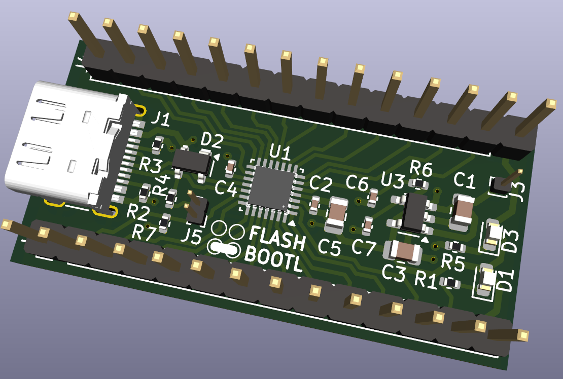
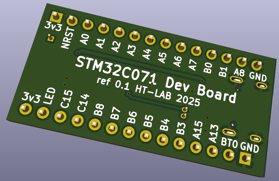
This repository contains a tiny STM32C071G8U6N development board developed in KiCAD8. The board took just 1 day to develop and another few hours sorting out some JLCPCB issues (wrong/shifted part alignments, selecting parts from LCSC etc).
Note this board has not yet been manufacturered (JLCPCB gave a quote for £47{UK} for 5 Boards).
The boards is nothing more but a USB-C connector, STM32C071 and a 3.3v power regulator. Schematics/PBC/Manufacturing data is located in the KiCAD directory.
See the LICENSE file for details.
STM32 is a registered trademark of STMicroelectronics International N.V.
| Qty | Value | Footprint | References |
|---|---|---|---|
| 4 | 100nF | Capacitor_SMD:C_0402_1005Metric | C2, C4, C6, C7 |
| 3 | 1K5 | Resistor_SMD:R_0402_1005Metric | R1, R4, R5 |
| 2 | 10K | Resistor_SMD:R_0402_1005Metric | R6, R7 |
| 2 | 1uF | Capacitor_SMD:C_0805_2012Metric | C1, C3 |
| 2 | 5K1 | Resistor_SMD:R_0402_1005Metric | R2, R3 |
| 2 | Conn_01x14_Pin | Connector_PinHeader_2.54mm:PinHeader_1x14_P2.54mm_Vertical | J2, J4 |
| 2 | LED | LED_SMD:LED_0603_1608Metric | D1, D3 |
| 1 | 4.7uF | Capacitor_SMD:C_0805_2012Metric | C5 |
| 1 | Conn_01x01_Pin | Connector_PinHeader_1.00mm:PinHeader_1x01_P1.00mm_Vertical | J3 |
| 1 | Conn_01x02_Pin | Connector_PinHeader_1.00mm:PinHeader_1x02_P1.00mm_Vertical | J5 |
| 1 | SP0503BAHT | Package_TO_SOT_SMD:SOT-143 | D2 |
| 1 | STM32C071G8UxN | Package_DFN_QFN:QFN-28_4x4mm_P0.5mm | U1 |
| 1 | TPS73633DBV | Package_TO_SOT_SMD:SOT-23-5 | U3 |
| 1 | USB_C_Receptacle_USB2.0_14P | ht-lab:USB_C_Receptacle_G-Switch_GT-USB-7010ASV_mod | J1 |
It measures 38.4 × 19.3 mm and has 2 copper layers, 1.6 mm thick.
24 parts, built around the TPS73633DBV and SP0503BAHTG. The full list of its parts is on this page, with links to each part's symbol and footprint where PCBKit's library has them.
From the htminuslab/STM32C071_Dev_Board repository on GitHub, at the commit this page was made from: the board is KiCAD/stm32c071devboard.kicad_pcb and its schematic KiCAD/stm32c071devboard.kicad_sch. PCBKit opens the board in the browser, with nothing to install.
Its repository publishes it under the MIT licence: you may reuse it on that licence's terms (keep the author's notice, and for a copyleft licence share your changes alike).


FeruzTopalov/eleph
GPS-based local relative navigation system for group of up to 6 members


fsnitz/CcSoM
An open source system on chip based on the GateMate FPGA from Cologne Chip (Supports: CCGM1A1 & CCGM1A2)


hanebefl/wandfernsprecher-hw
GSM conversion for a old German Wandfernsprecher telephone

Volkov997/pen-card
RF Pentesting tool, but small enough for your wallet. Features: Wifi & Bluetooth, NFC, IR, (Sub Ghz, Planned)