2 layers28.3 × 39.8 mm
LevelShifter
gusmanb/logicanalyzer
24 channel, 100Msps logic analyzer hardware and software
21 parts5.1kGPL-3.0

 HTangl/DIDIY8
All in one board for smash rectangle controllers
DIDIY V1 is an open-source printed circuit board by HTangl, from the HTangl/DIDIY repository on GitHub. It is a 2-layer board of 75 × 51.5 mm with 21 parts on 37 nets, routed with 168 tracks and 0 vias.
Its parts include 11 connectors and 1 IC. It belongs with the RP2040 boards of this library.
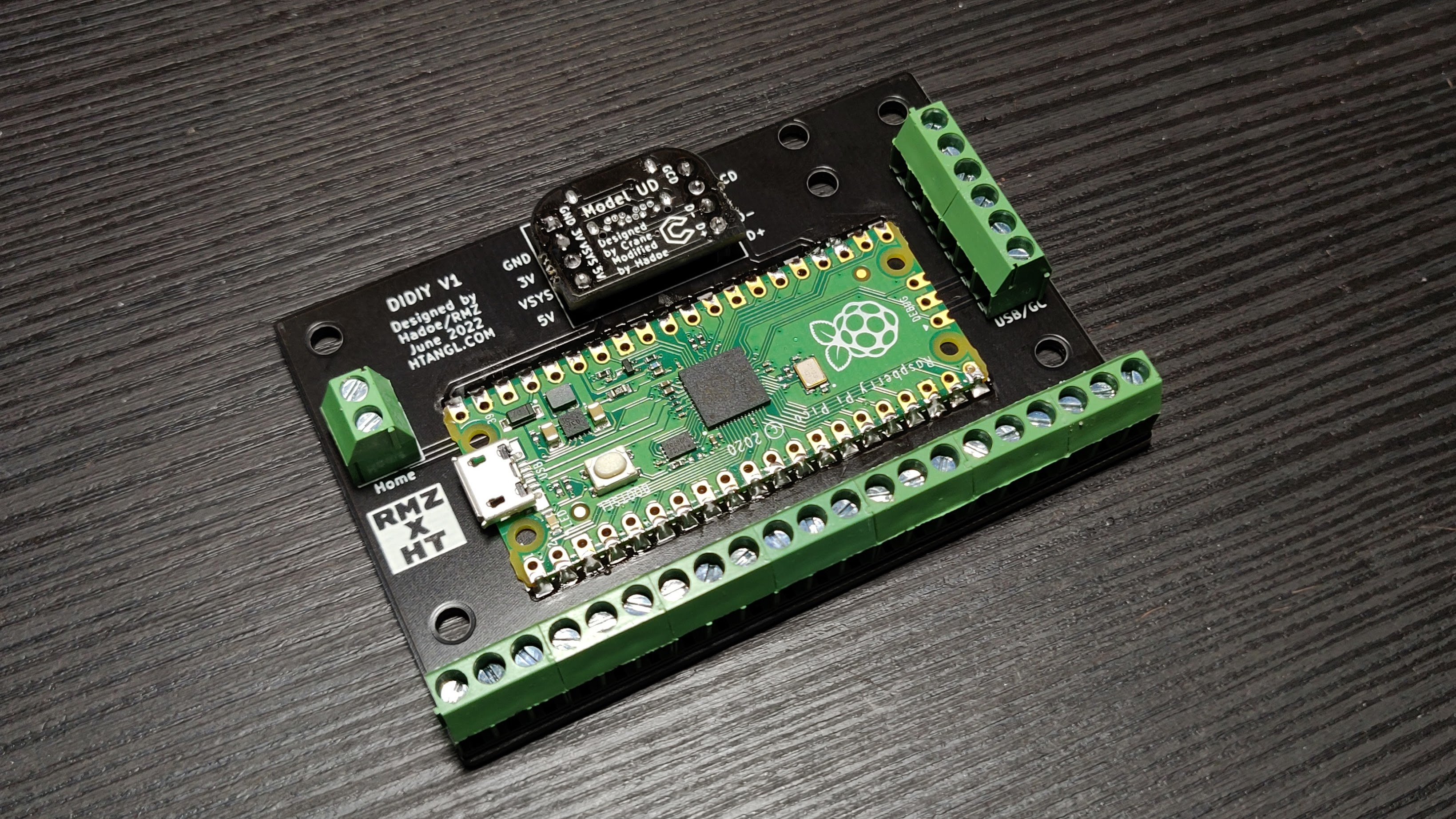
The DIDIY is an all in one board designed to make building a rectangle controller much more simple and straightforward.
If you’d like to assemble one of these boards yourself this repository contains the files necessary to order the boards from JLCPCB. They have a 5 board minimum order but the boards are pretty cheap.
Download the files in this repo by clicking on the green code button in the top right corner and then click on “Download ZIP”. Unzip the folder and grab the gerber zip file from the fabrication folder. Do not unzip the gerber zip file.
Go to https://jlcpcb.com/ and click “Order now” at the top right. Click on the blue “Add gerber file” button and upload the gerber zip file.
You can leave all of the options set to default. Only thing you might want to change is the pcb color, this doesn’t add cost but it does increase production time. All you have to do now is click “SAVE TO CART” on the right and finish the checkout process. I recommend using DHL shipping, it’s expensive but has proven to be very reliable.
1 - Raspberry Pi Pico
1 - Model UD, these can also be ordered from JLCPCB, there’s an ordering guide on the Model UD github page. The Model UD isn't absolutely required, you can instead simply hard wire a USB or GC cable to the USB/GC pin bank on the right, there are 2 holes at the top right that can be used to zip tie the cable in place as well.
9 - 3 pin 3.5mm pitch screw terminal
1 - 2 pin 3.5mm pitch screw terminal
1 – Set of 2.54 pitch male pin headers
Before soldering anything you should test your Pico by uploading firmware onto it, I recommend using the Htangl Firmware.
Here is a guide on how to get the DIDIY set up on Slippi and Wii/Switch after you have completed the build - https://www.htangl.com/didiy-guide
Although both HayBox and Pico Rectangle can be used on the DIDIY you will have to change the pinout file if you intend to use either of them.
Start by soldering the Pico USB data pads to the DIDIY. These are the 2 small pads underneath the usb port labeled as TP2 and TP3. Add a small amount of solder to both of the pads as well as the correlating through holes on the DIDIY.
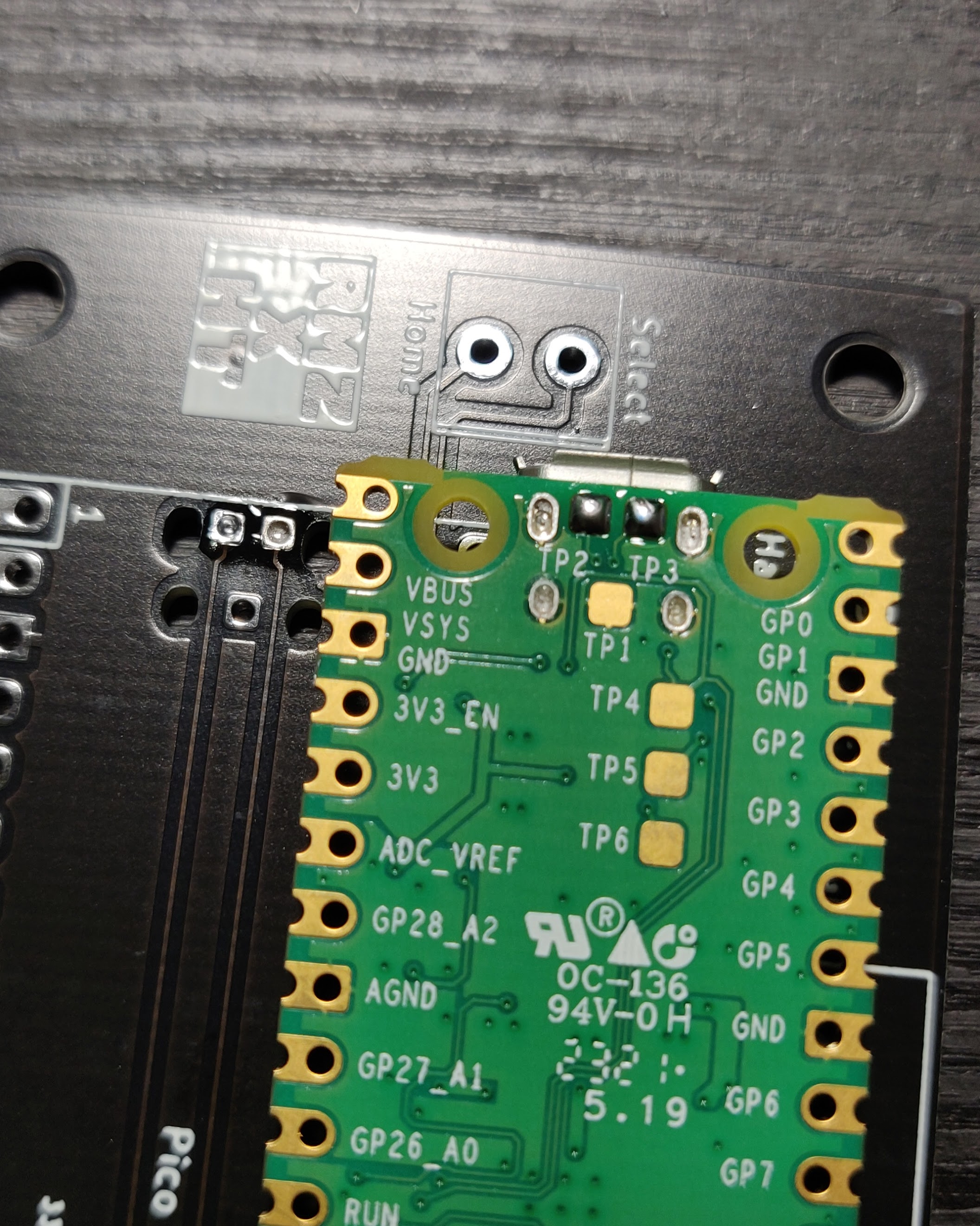
You will now need to align the Pico to the DIDIY board, I use a breadboard to do this but it’s not required. You can just stick pin headers through the top of the Pico and then through the didiy and flip the boards over together. Now press the DIDIY down into the Pico and heat up the through holes that connect to the data pads. You are trying to melt the solder on the Pico pads so that it fuses to the through holes on the DIDIY. I usually hold my iron on each hole for about 2-3 seconds and alternate between them a few times.
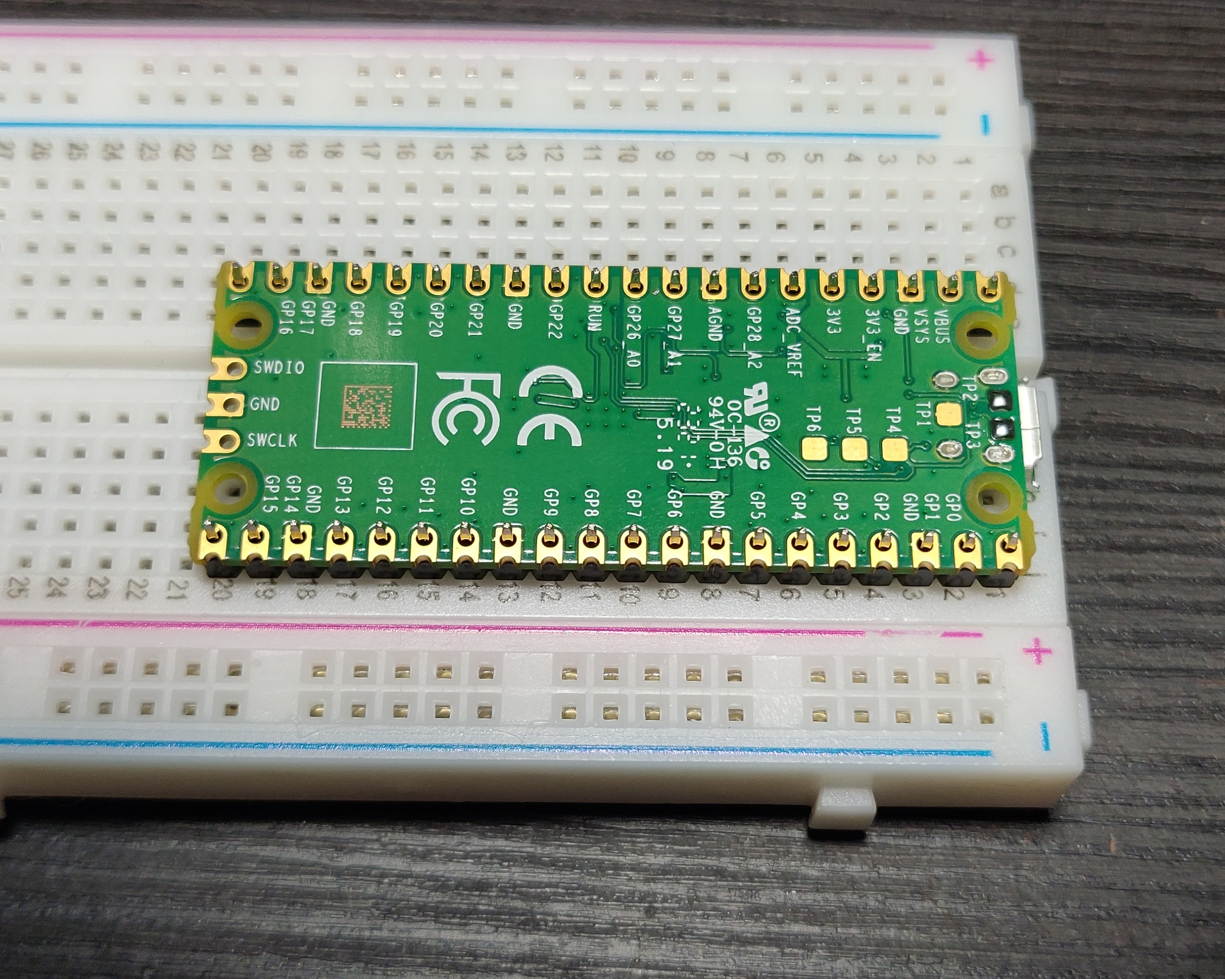
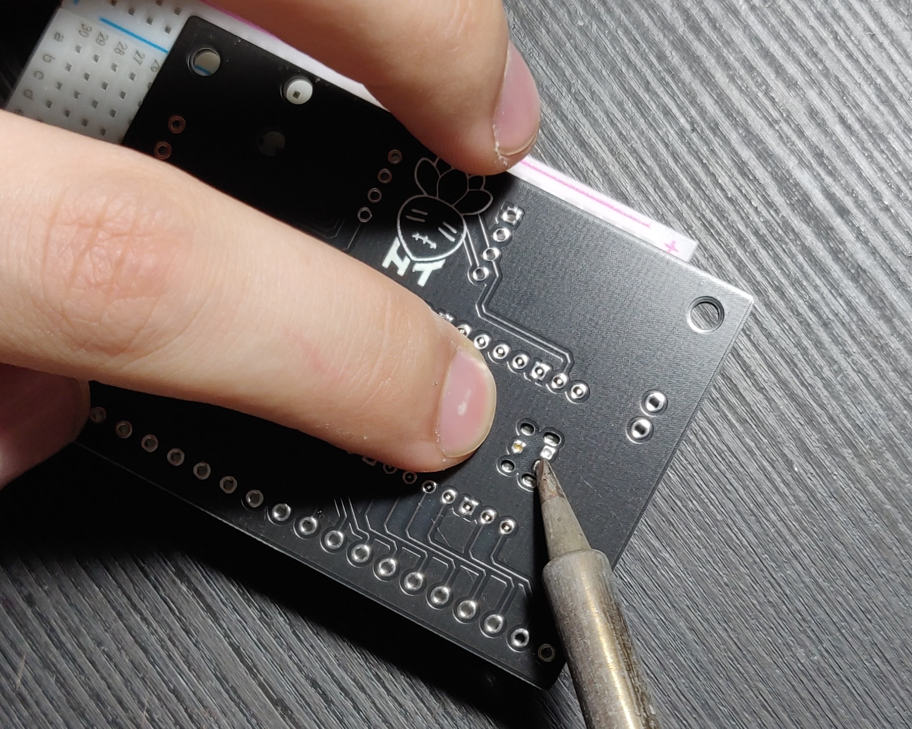
Remove the pin headers and flip the board over. The Pico should be flat against the DIDIY, if it isn’t re insert the pin headers and try heating up the through holes a little longer. It’s a good idea to now check to see if the pads on the Pico are properly connected to the DIDIY. To do this you’ll need a multi meter with a continuity test mode. Test between the tiny pins on the back of the Pico USB and the D+/D- pins on the DIDIY (you can use either set of data pins on the DIDIY). If you have continuity on both pins you’re good to go and you can move on to the next step. If not try repeating step 2.
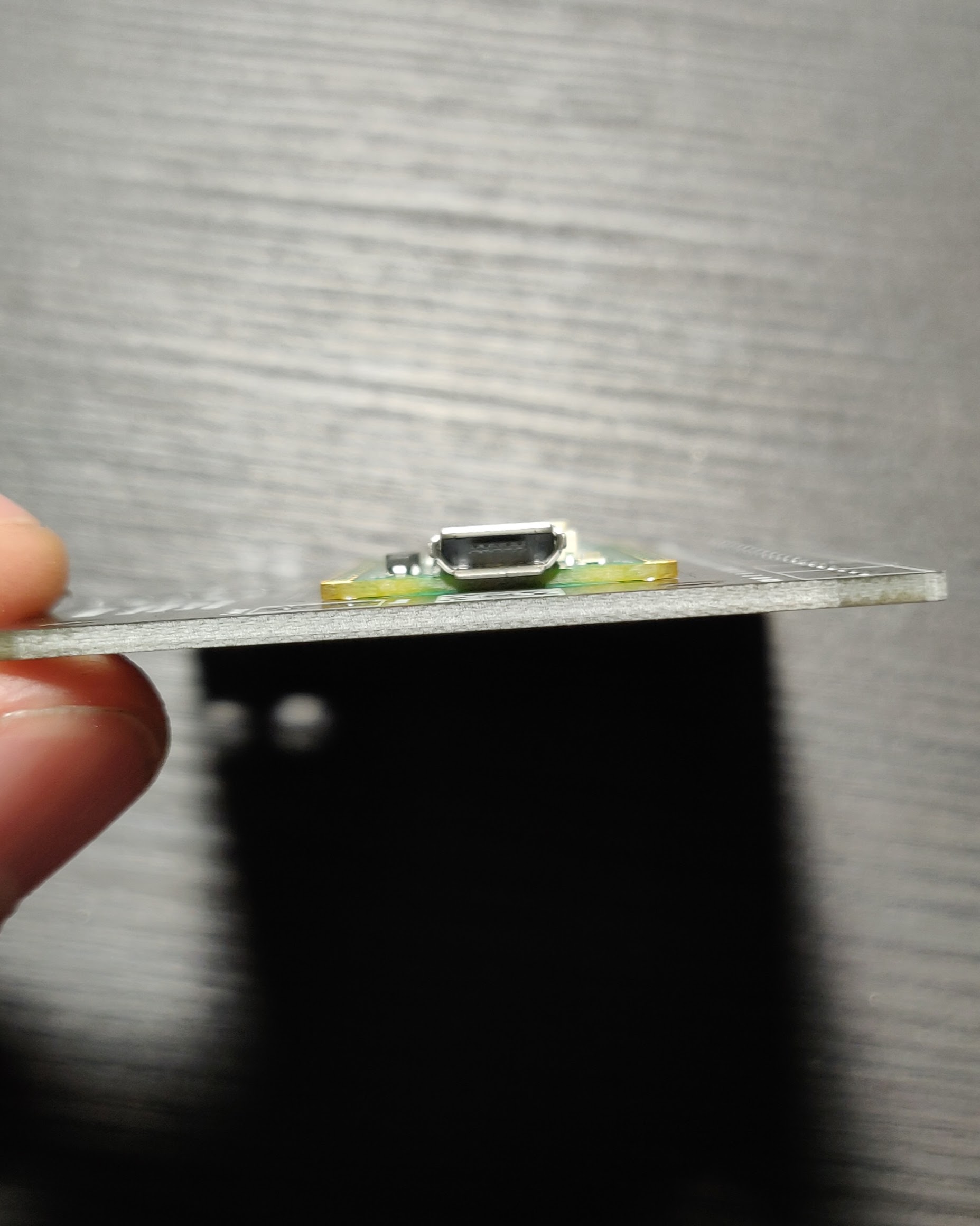
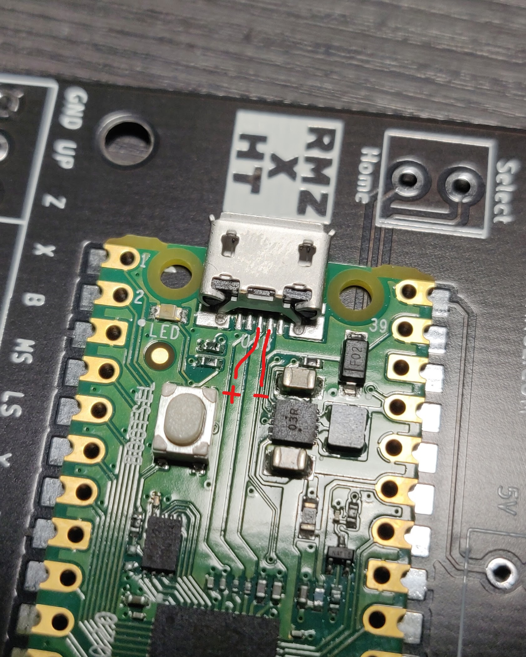
Next solder all the pins on the Pico. I recommend soldering any 2 pins on opposite sides near the back side of the Pico furthest from the micro usb port. The back end can sometimes stick up a little bit even if you soldered the data pins properly so it helps to solder pins at the back while pressing the Pico down to make sure it’s perfectly flat against the DIDIY.
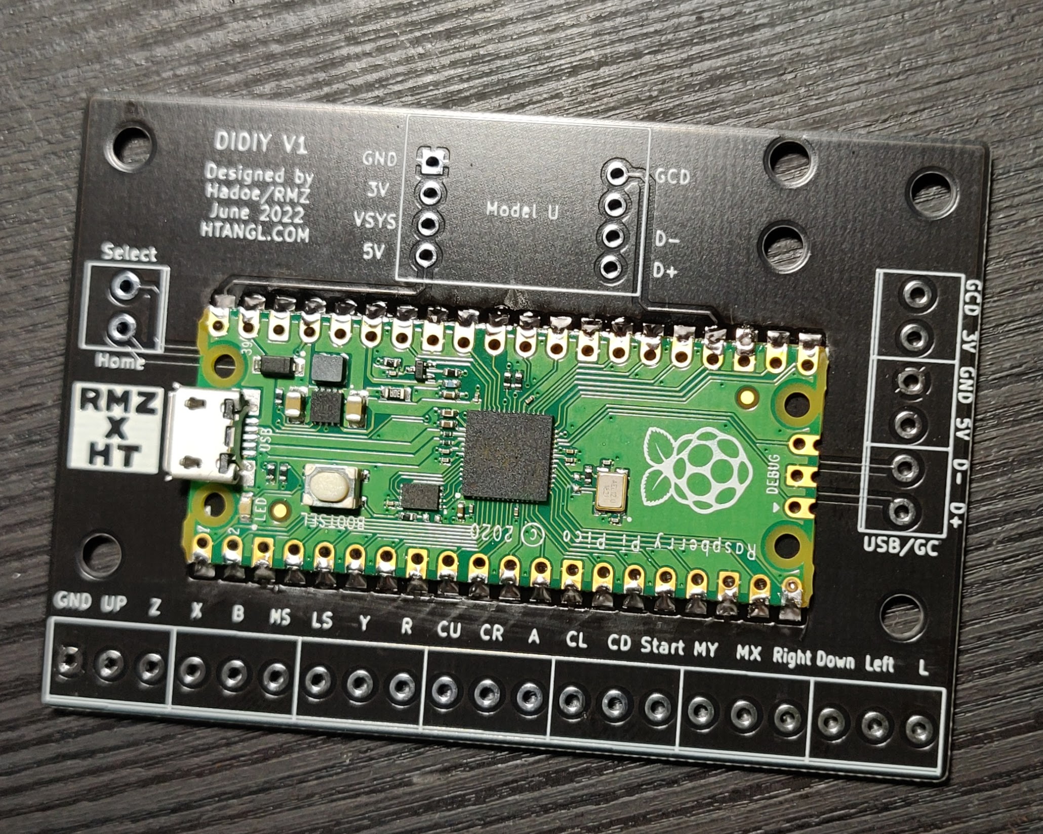
Now solder the Model UD to the DIDIY. Start by inserting 2 rows of 4 pin headers with the short side facing towards the top of the board, the plastic spacers should be on the top side. You can either solder the pins to the DIDIY then put the Model UD on and solder it to the pins or vice versa. I usually solder the pins to the DIDIY first but do whatever is easiest for you, just make sure the Model UD is mounted with the USB port facing down and be careful not to tilt it while soldering. The pins should poke through the Model UD holes an even amount on both sides.
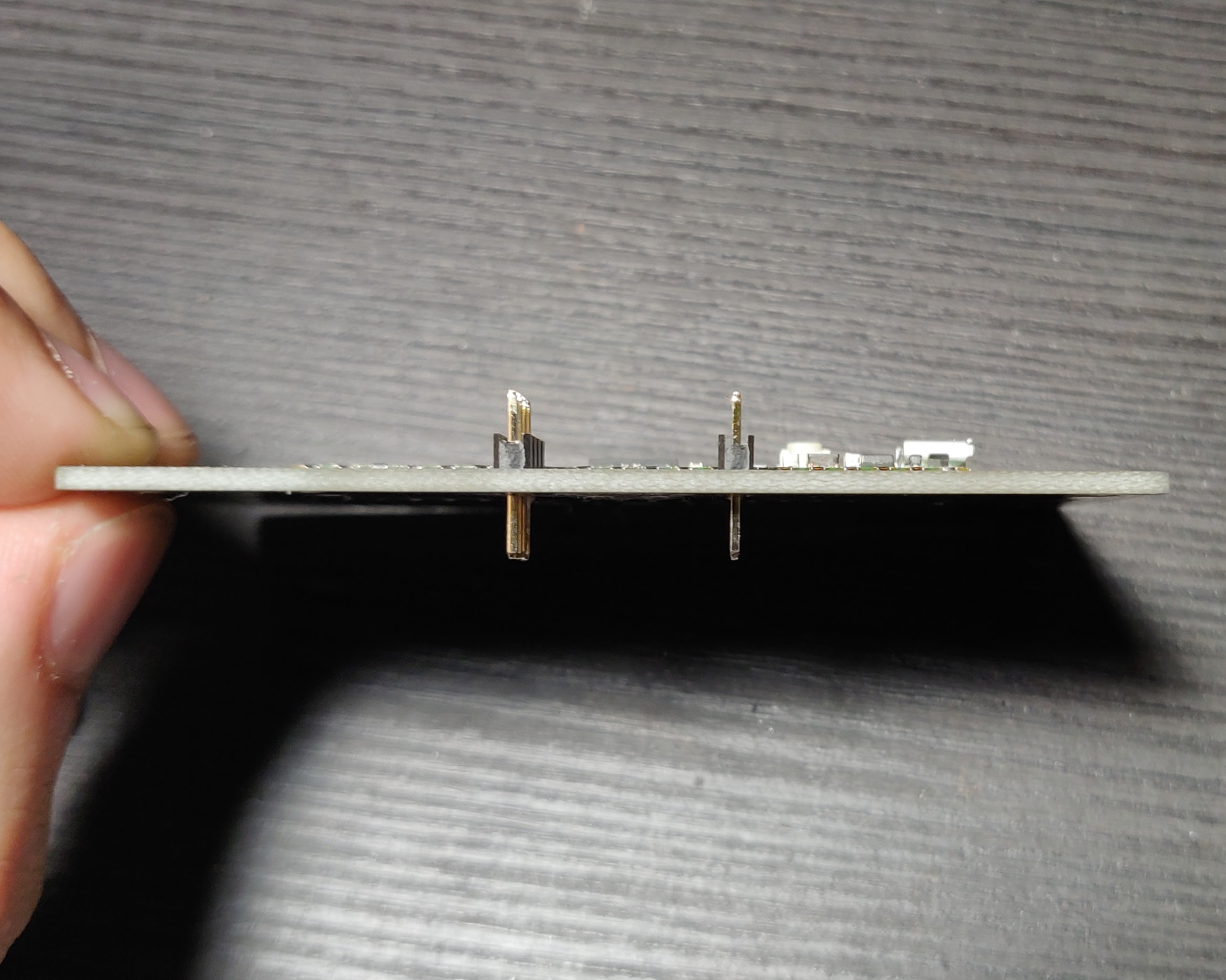
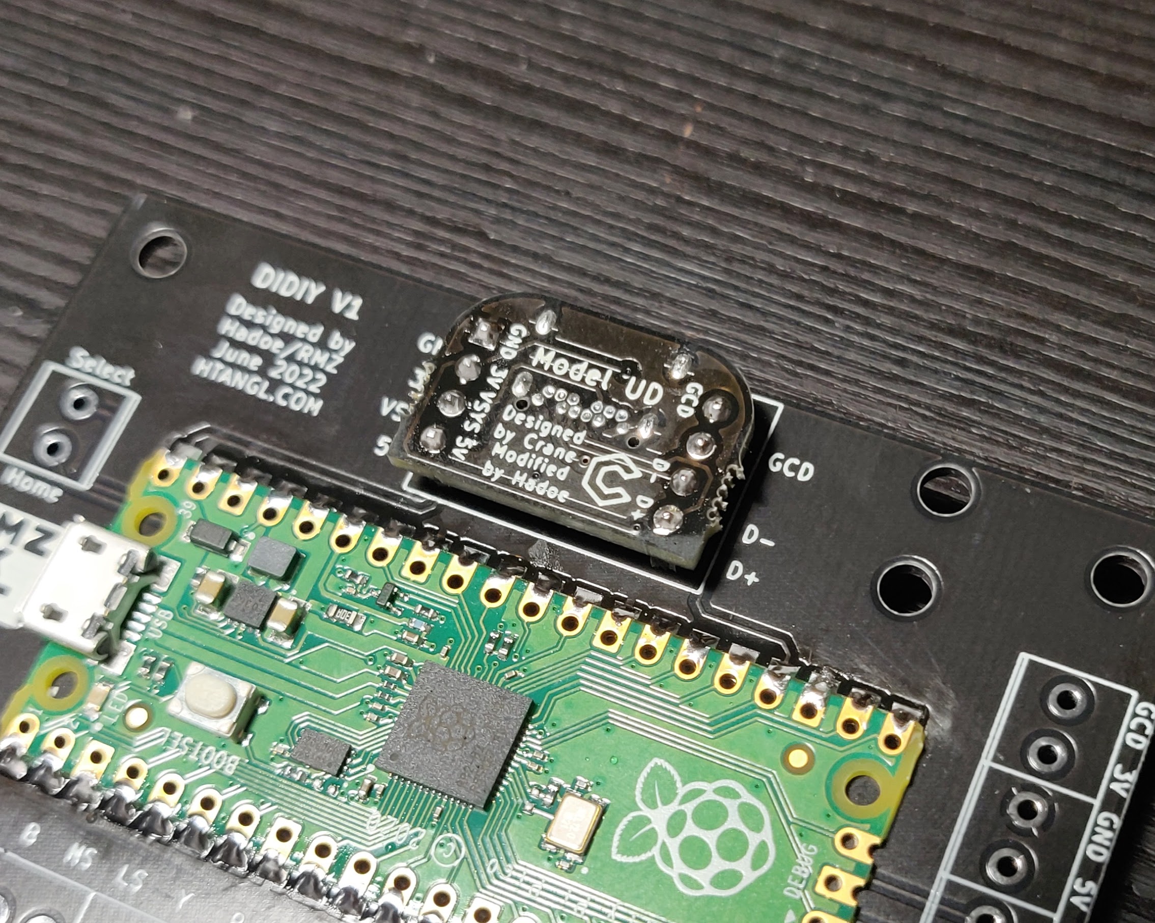
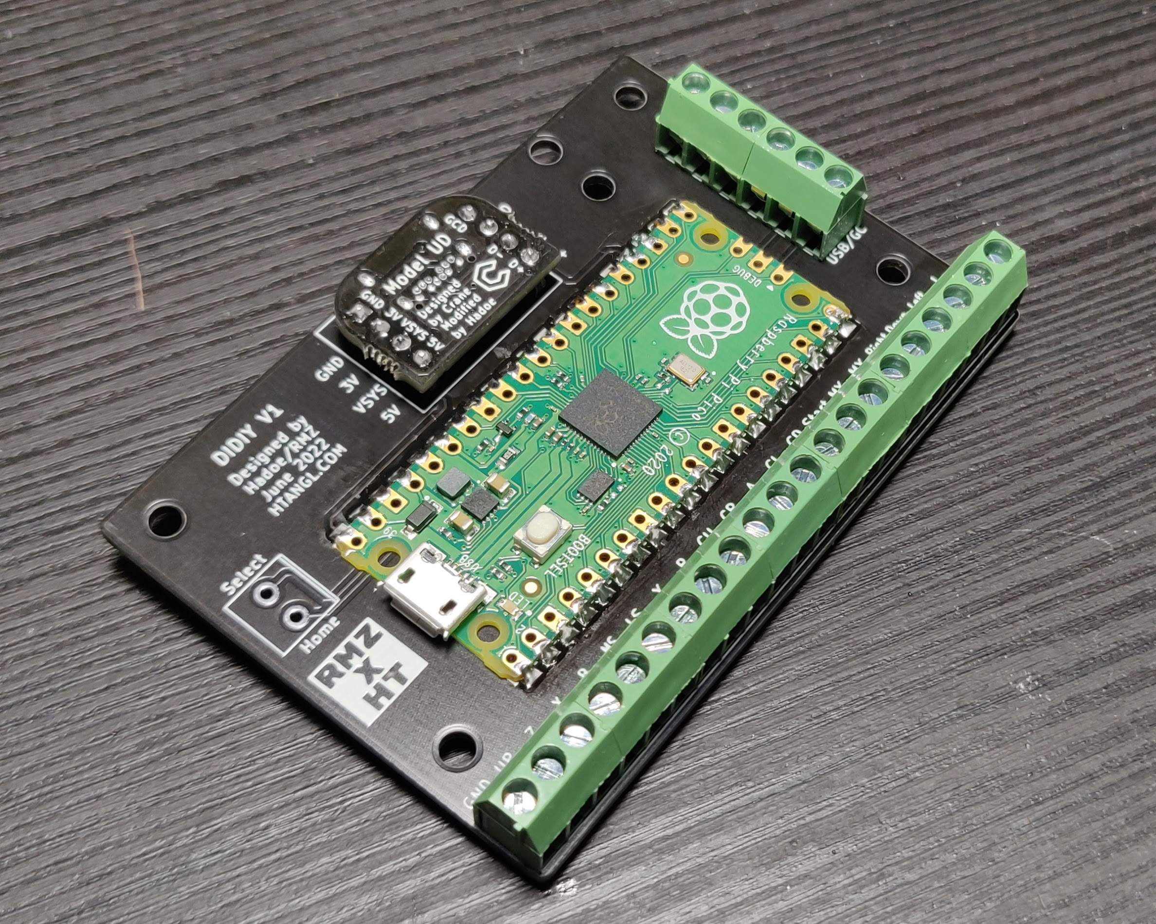
Last step is to solder all the screw terminals on. Start by attaching 7 of the 3 pin terminals together, they can be a little tricky to slide together so make sure they’re flush to each other. Now attach another 2 3 pin terminals together for the USB/GC pin bank, if you aren’t going to hardwire a GC or USB cable you do not need to install these terminals. Insert all of the terminals into the board and solder them in place, the picture doesn’t show the 2 pin terminal but it’s used for the Select/Home buttons. Also note that I face the USB/GC and Select/Home terminals inwards towards the middle of the DIDIY. This is in an effort to keep wires from running out the sides of the board but is purely a preference thing, you can face them outwards if you like.
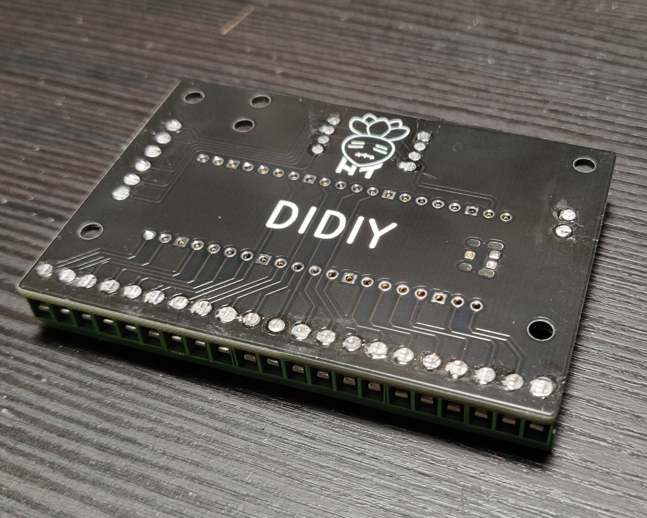
All that’s left now is snipping off the excess pins sticking out the back of the board. Use a pair of flush cutters to cut them. The pins like to go flying off when cut so I line up the cutters then put a towel over top of the board and then snip one pin. Repeat until all the pins are flush.
This repository is licensed under the CERN Open Hardware Licence Version 2 - Strongly Reciprocal. Please read the license in this repository and visit https://ohwr.org/cernohl for more information. This license allows you to make a modified or unmodified version of the board for yourself or to sell provided you follow the guidelines of the license. The strongly reciprocal version of the license I have chosen requires that you use this same license if you decide to make modifications to any of the files in this repository.
| Qty | Value | Footprint | References |
|---|---|---|---|
| 2 | Conn_01x03 | Didiy:Degson_DG350_1X03_Screw_Terminal | J3, J4 |
| 1 | Buttons 1 | Didiy:Degson_DG350_1X03_Screw_Terminal | J5 |
| 1 | Buttons 2 | Didiy:Degson_DG350_1X03_Screw_Terminal | J6 |
| 1 | Buttons 3 | Didiy:Degson_DG350_1X03_Screw_Terminal | J7 |
| 1 | Buttons 4 | Didiy:Degson_DG350_1X03_Screw_Terminal | J8 |
| 1 | Buttons 5 | Didiy:Degson_DG350_1X03_Screw_Terminal | J9 |
| 1 | Buttons 6 | Didiy:Degson_DG350_1X03_Screw_Terminal | J10 |
| 1 | Buttons 7 | Didiy:Degson_DG350_1X03_Screw_Terminal | J11 |
| 1 | Conn_01x02 | Didiy:Degson_DG350_1X02_Screw_Terminal | J2 |
| 1 | LOGO | PCBArt:RMZ X HT 4 | G*** |
| 1 | LOGO | PCBArt:RMZ X HT 6 | G*** |
| 1 | LOGO | HTangl:HTurnip_Small | G*** |
| 1 | Model U | HTangl:Model_UD_Header | J1 |
| 1 | Pico | Pico:RPi_Pico_Removed3Pins | U1 |
The 15 most common of 21 parts.
It measures 75 × 51.5 mm and has 2 copper layers, 1.6 mm thick.
21 parts. The full list of its parts is on this page, with links to each part's symbol and footprint where PCBKit's library has them.
From the HTangl/DIDIY repository on GitHub, at the commit this page was made from: the board is Kicad/DIDIY V1.kicad_pcb and its schematic Kicad/DIDIY V1.kicad_sch. PCBKit opens the board in the browser, with nothing to install.
Its repository states no licence, so its author keeps all rights: ask HTangl before reusing the design.
gusmanb/logicanalyzer
24 channel, 100Msps logic analyzer hardware and software

mntmn/amiga2000-gfxcard
MNT VA2000, an Open Source Amiga 2/3/4000 Graphics Card (Zorro II/III), written in Verilog


hackclub/OnBoard
💡 Join 1,000 teenagers and make your first PCB with a $100 grant!

drandyhaas/KiCadRoutingTools
A set of Python/Rust tools to aid routing in KiCad

Arrow-air/project-quiver
Project Quiver documentation, designs, and project artifacts.

