
4 layers113.5 × 105.5 mm
Multistepper
eddyem/stm32samples
Code samples and ready projects based on bare-metal STM32
243 parts208

 honzup/LCC_Interface_KiCad
LCC/OpenLCB CAN interface board (KiCad): TCAN332, dual RJ45, termination jumper, test points, LEDs (mirror of Forgejo)
LCC Interface is an open-source printed circuit board by honzup, from the honzup/LCC_Interface_KiCad repository on GitHub, published under the CERN-OHL-P-2.0 licence. It is a 2-layer board of 60 × 50 mm with 27 parts on 16 nets, routed with 197 tracks and 5 vias.
It is built around the PESD1CAN. Its parts include 6 resistors, 4 diodes, 3 connectors, 2 capacitors and 1 IC. It belongs with the interfaces and adapters boards of this library.
A small two-layer board that connects any 3.3 V microcontroller with a CAN controller (ESP32 TWAI, STM32, …) to an LCC / OpenLCB bus using standard RJ45 cables. Designed in KiCad for model railway layouts; in daily use on my layout under every LCC node and the Ethernet bridge (lcc-eth-bridge).
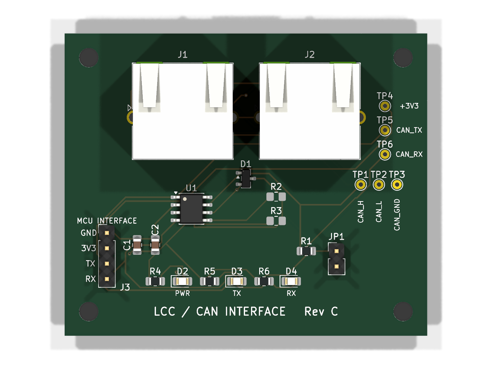
Why a dedicated board rather than a ready-made transceiver module:
-5385 (LED) variant either.| Pin | Signal | T568B colour |
|---|---|---|
| 1 | CAN_H | white/orange |
| 2 | CAN_L | orange |
| 3 | CAN_GND | white/green |
| 4 | ALT_L (pass-through) | blue |
| 5 | ALT_H (pass-through) | white/blue |
| 6 | CAN_GND | green |
| 7 | PWR_NEG (pass-through) | white/brown |
| 8 | PWR_POS (pass-through) | brown |
| shell | CAN_GND |
CAN_H/CAN_L share one twisted pair, so ordinary straight-through Cat5e/Cat6 patch leads work. Never use crossover or flat (untwisted) cable.
LCC_Interface_RevC_gerbers.zip to any fab (JLCPCB, PCBWay …):
2 layers, 1.6 mm, default settings.BOM.csv (with Digi-Key part numbers) and digikey-order.txt
(paste into Digi-Key's quick order). bom/ibom.html is an interactive BOM –
open it in a browser while soldering to highlight each part's position.With the board powered and connected to the bus:
| Check | Expect |
|---|---|
| PWR LED | on |
| 3V3 test point (TP4) | 3.3 V |
| CAN_H and CAN_L to CAN_GND, bus idle | both ≈ 1.9 V – normal for a 3.3 V transceiver, not the 2.5 V of 5 V parts |
| TX / RX test points, bus idle | ≈ 3.3 V (high = recessive) |
| RX LED | flickers on any bus traffic |
| TX LED | flickers only when this node transmits |
| CAN_H ↔ CAN_L, everything powered off | ≈ 60 Ω with both ends terminated; ≈ 120 Ω means only one end |
RX flickering with TX dark means the node hears the bus but isn't transmitting – check the TX wire and the node firmware.
| File | What |
|---|---|
LCC_Interface.kicad_pro / .kicad_sch / .kicad_pcb | KiCad project (made in KiCad 10; the schematic is the source of truth) |
LCC_Interface_RevC_gerbers.zip (+ unzipped folder) | Gerbers and drill files for ordering |
BOM.csv, digikey-order.txt, bom/ibom.html | Bill of materials, Digi-Key order, interactive BOM |
images/ | Renders |
rev-c.rev-b.CERN Open Hardware Licence v2 – Permissive (CERN-OHL-P-2.0) – see LICENSE.
| Qty | Value | Footprint | References |
|---|---|---|---|
| 6 | TP | TestPoint:TestPoint_THTPad_D1.5mm_Drill0.7mm | TP1, TP2, TP3, TP4, TP5, TP6 |
| 4 | MountingHole:MountingHole_3.2mm_M3 | H1, H2, H3, H4 | |
| 3 | 1k | Resistor_SMD:R_0805_2012Metric_Pad1.20x1.40mm_HandSolder | R4, R5, R6 |
| 3 | LED | LED_SMD:LED_0805_2012Metric_Pad1.15x1.40mm_HandSolder | D2, D3, D4 |
| 2 | 10k DNP | Resistor_SMD:R_0805_2012Metric_Pad1.20x1.40mm_HandSolder | R2, R3 |
| 2 | LCC RJ45 | Connector_RJ:RJ45_Amphenol_RJHSE5380 | J1, J2 |
| 1 | 100nF | Capacitor_SMD:C_0805_2012Metric_Pad1.18x1.45mm_HandSolder | C1 |
| 1 | 120R | Resistor_SMD:R_0805_2012Metric_Pad1.20x1.40mm_HandSolder | R1 |
| 1 | 4.7uF | Capacitor_SMD:C_0805_2012Metric_Pad1.18x1.45mm_HandSolder | C2 |
| 1 | MCU INTERFACE | Connector_PinHeader_2.54mm:PinHeader_1x04_P2.54mm_Vertical | J3 |
| 1 | PESD1CAN | Package_TO_SOT_SMD:SOT-23 | D1 |
| 1 | TCAN332DR | Package_SO:SOIC-8_3.9x4.9mm_P1.27mm | U1 |
| 1 | TERM ENABLE | Connector_PinHeader_2.54mm:PinHeader_1x02_P2.54mm_Vertical | JP1 |
eddyem/stm32samples
Code samples and ready projects based on bare-metal STM32

NewTec-GmbH/esp32-can-iot
A ESP32 based interface between CAN-bus and IoT environments.


frc971/electrical
This repo contains the electrical files for the 971 FRC team. The files include PCBs and the electrical system diagrams. The PCBs are created using KiCad.
It measures 60 × 50 mm and has 2 copper layers, 1.6 mm thick.
27 parts, built around the PESD1CAN. The full list of its parts is on this page, with links to each part's symbol and footprint where PCBKit's library has them.
From the honzup/LCC_Interface_KiCad repository on GitHub, at the commit this page was made from: the board is LCC_Interface.kicad_pcb and its schematic LCC_Interface.kicad_sch. PCBKit opens the board in the browser, with nothing to install.
Its repository publishes it under the CERN-OHL-P-2.0 licence: you may reuse it on that licence's terms (keep the author's notice, and for a copyleft licence share your changes alike).