2 layers99.1 × 99 mm
XDuinoRail Debug
chatelao/xDuinoRail-Decoder
The friendly decoder development plattform for model railroad tinkers.
170 partsAGPL-3.0

 hoffy98/RobotRubi
A complete Rubik's Cube solving robot designed from scratch
RobotRubi is an open-source printed circuit board by hoffy98, from the hoffy98/RobotRubi repository on GitHub. It is a 4-layer board of 176.8 × 89.4 mm with 149 parts on 141 nets, routed with 878 tracks and 256 vias.
It is built around the AMS1117-3.3, S8050 and S8550, with the SS34 and B140-E3 among its other parts. Its parts include 43 connectors, 39 resistors, 22 capacitors, 18 diodes and 15 transistors. It belongs with the robots and motor control boards and the STM32 boards of this library.



A complete Rubik's Cube solving robot designed from scratch
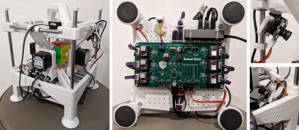
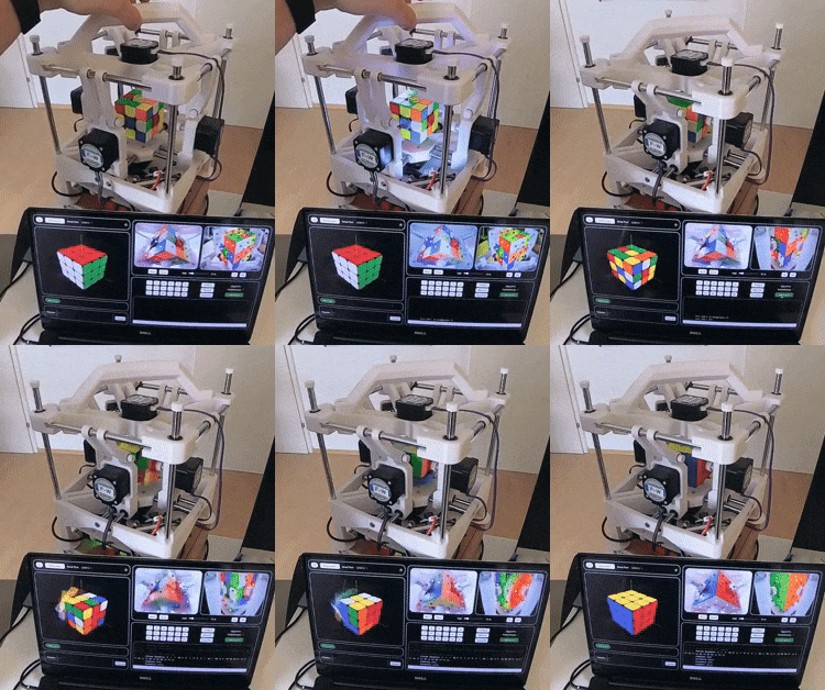
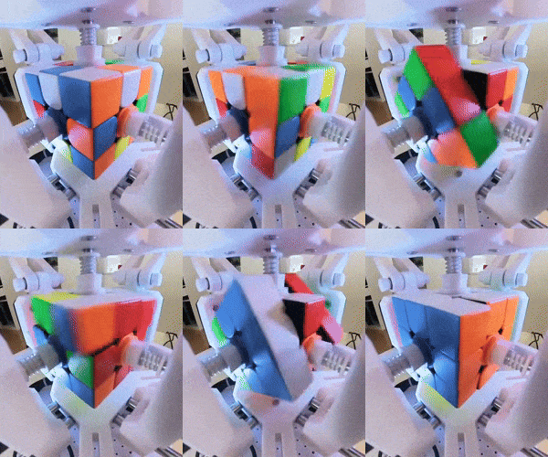
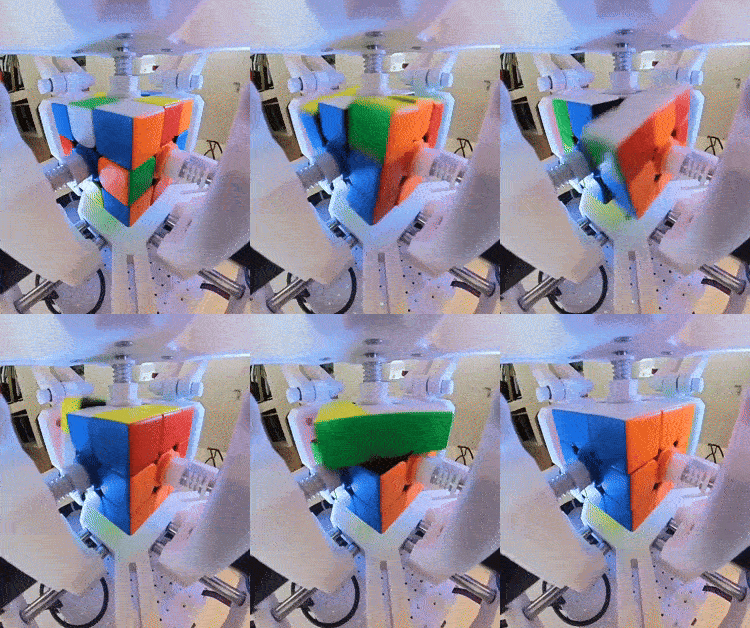
Robot-Rubi is a fully autonomous Rubik's cube solving robot that combines mechanical engineering, electronics design, computer vision, and advanced algorithms. The entire system was designed and built from the ground up, featuring custom 3D-printed mechanics, a purpose-built PCB, and an optimized solving algorithm.
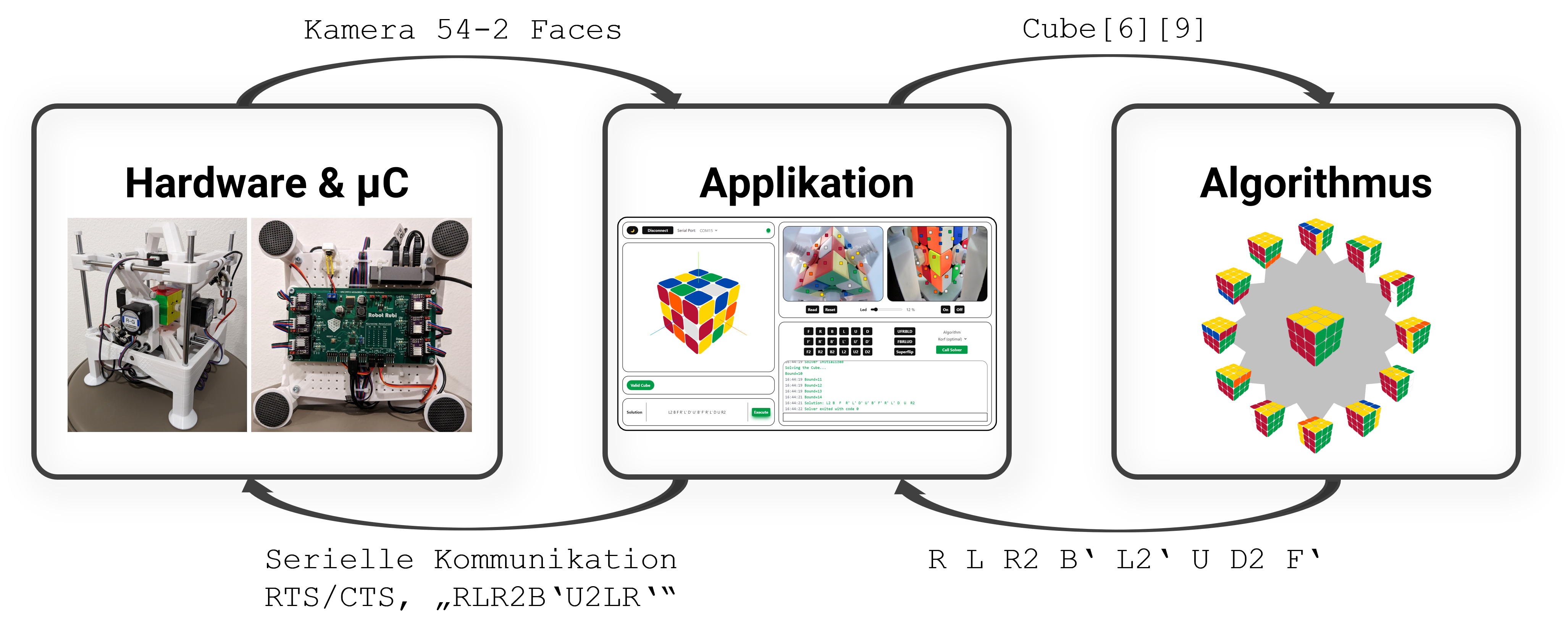
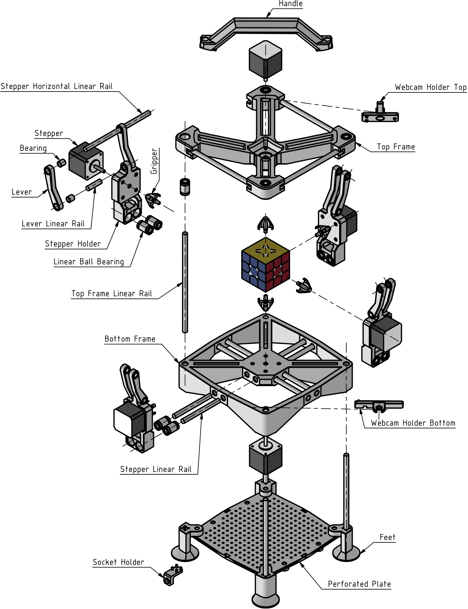
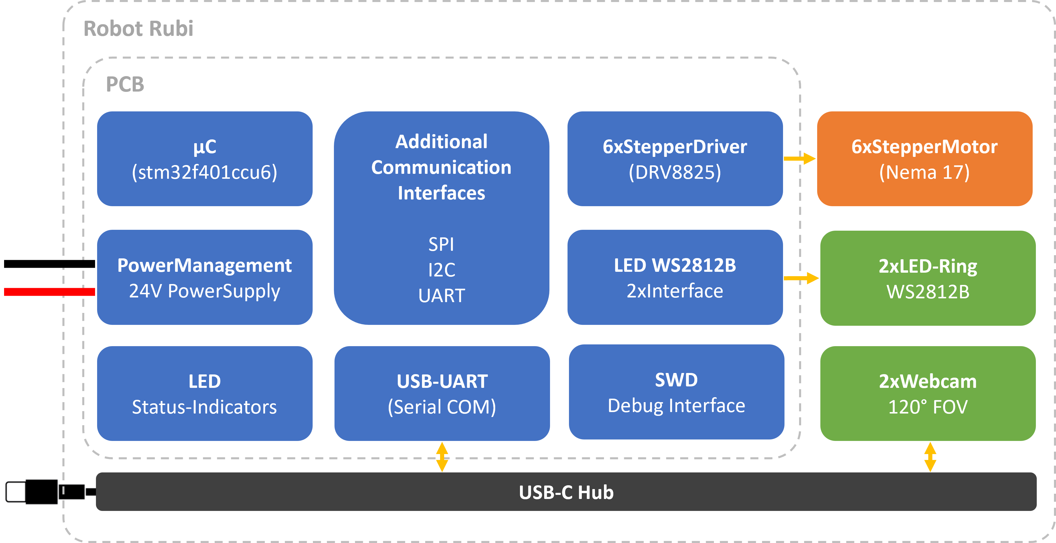
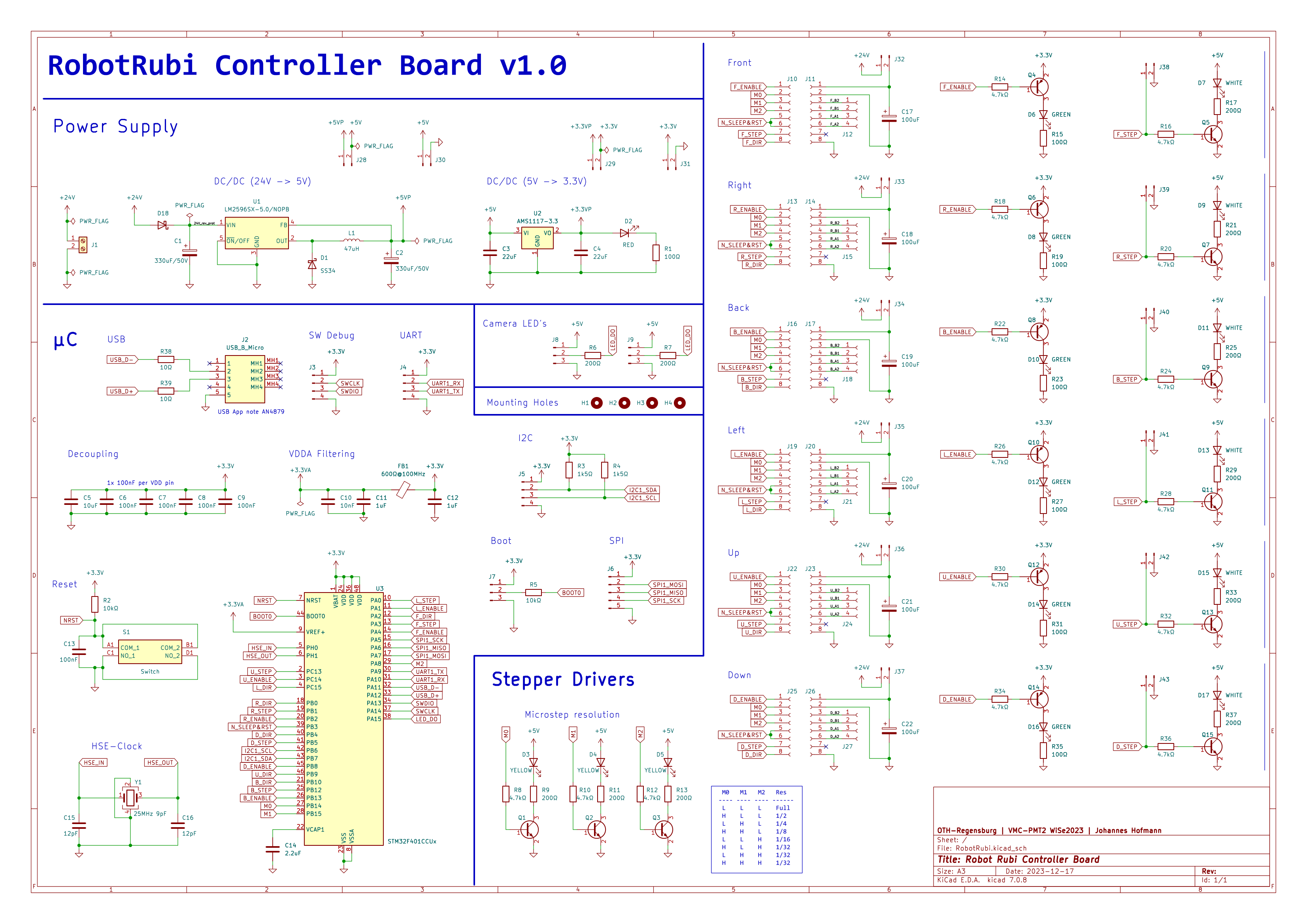
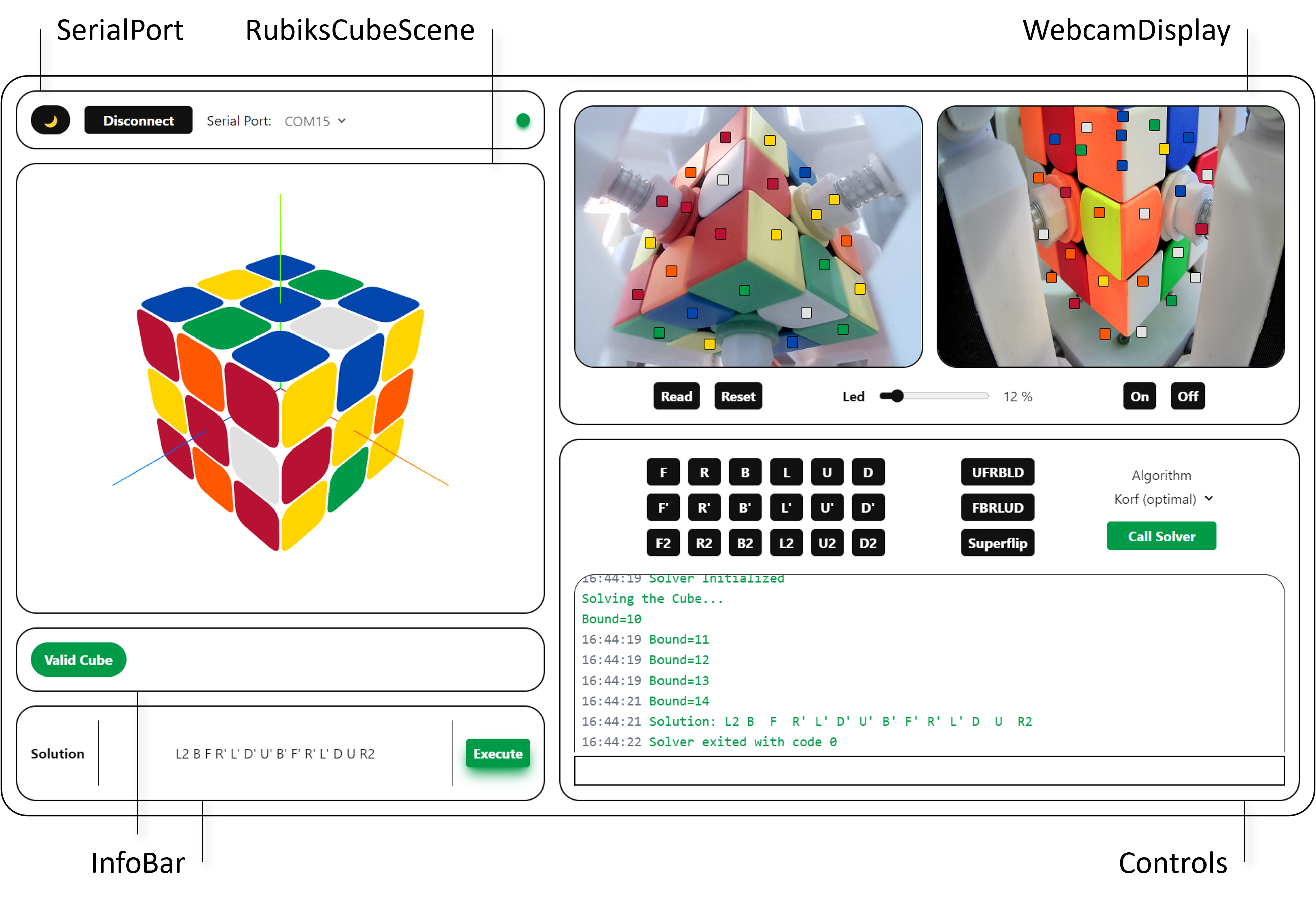
RobotRubi
├───algorithm/          # Solving algorithms and pattern databases
│   ├───src/           # C++ implementation of IDA* solver
│   ├───docs/          # Algorithm documentation and research papers
│   └───performance/   # Performance analysis and benchmarks
├───docs/              # Complete project documentation
│   ├───chapters/      # Detailed technical documentation
│   ├───images/        # Project images and diagrams
│   └───main.pdf       # Full project report (German)
├───embedded/          # Hardware design and microcontroller firmware
│   ├───Hardware/      # PCB schematics and design files
│   └───Software/      # STM32 firmware implementation
├───frontend/          # Desktop application
│   ├───electron/      # Cross-platform desktop app
│   └───sandbox/       # Development and testing
└───mechanical/        # CAD files and 3D models
    ├───parts/         # Individual component designs
    ├───subassembly/   # Assembly drawings
└───testPrintParts/ # Prototype iterationsThis project demonstrates expertise across multiple engineering disciplines:
Comprehensive documentation is available in the docs/ folder, including:
docs/main.pdf)This project was developed as a comprehensive engineering challenge, combining the fascination of the Guinness World Record for fastest Rubik's cube solving (0.38 seconds by MIT, 2018) with the educational goal of understanding every aspect of such a system from first principles.
| Qty | Value | Footprint | References |
|---|---|---|---|
| 16 | Conn_01x02_Pin | Connector_PinHeader_2.54mm:PinHeader_1x02_P2.54mm_Vertical | J28, J29, J30, J31, J32, J33, J34, J35, J36, J37, J38, J39, J40, J41, J42, J43 |
| 15 | 4.7kΩ | Resistor_SMD:R_0603_1608Metric | R8, R10, R12, R14, R16, R18, R20, R22, R24, R26, R28, R30, R32, R34, R36 |
| 12 | Conn_01x08_Socket | Connector_PinSocket_2.54mm:PinSocket_1x08_P2.54mm_Vertical | J10, J11, J13, J14, J16, J17, J19, J20, J22, J23, J25, J26 |
| 11 | 200Ω | Resistor_SMD:R_0603_1608Metric | R6, R7, R9, R11, R13, R17, R21, R25, R29, R33, R37 |
| 9 | S8050 | Package_TO_SOT_SMD:SOT-23 | Q1, Q2, Q3, Q5, Q7, Q9, Q11, Q13, Q15 |
| 7 | 100Ω | Resistor_SMD:R_0603_1608Metric | R1, R15, R19, R23, R27, R31, R35 |
| 6 | 100uF | Capacitor_THT:C_Radial_D5.0mm_H11.0mm_P2.00mm | C17, C18, C19, C20, C21, C22 |
| 6 | Conn_01x04_Socket | Connector_JST:JST_EH_B4B-EH-A_1x04_P2.50mm_Vertical | J12, J15, J18, J21, J24, J27 |
| 6 | GREEN | LED_SMD:LED_0805_2012Metric | D6, D8, D10, D12, D14, D16 |
| 6 | S8550 | Package_TO_SOT_SMD:SOT-23 | Q4, Q6, Q8, Q10, Q12, Q14 |
| 6 | WHITE | LED_SMD:LED_0805_2012Metric | D7, D9, D11, D13, D15, D17 |
| 5 | 100nF | Capacitor_SMD:C_0402_1005Metric | C6, C7, C8, C9, C13 |
| 4 | MountingHole | MountingHole:MountingHole_4.3mm_M4 | H1, H2, H3, H4 |
| 3 | Conn_01x04_Pin | Connector_PinHeader_2.54mm:PinHeader_1x04_P2.54mm_Horizontal | J3, J4, J5 |
| 3 | YELLOW | LED_SMD:LED_0805_2012Metric | D3, D4, D5 |
| 2 | 10kΩ | Resistor_SMD:R_0402_1005Metric | R2, R5 |
| 2 | 10Ω | Resistor_SMD:R_0402_1005Metric | R38, R39 |
| 2 | 12pF | Capacitor_SMD:C_0402_1005Metric | C15, C16 |
| 2 | 1k5Ω | Resistor_SMD:R_0402_1005Metric | R3, R4 |
| 2 | 1uF | Capacitor_SMD:C_0402_1005Metric | C11, C12 |
| 2 | 22uF | Capacitor_SMD:C_0805_2012Metric | C3, C4 |
| 2 | 330uF/50V | Capacitor_SMD:CP_Elec_10x10.5 | C1, C2 |
| 2 | Conn_01x03_Pin | Connector_PinHeader_2.54mm:PinHeader_1x03_P2.54mm_Horizontal | J8, J9 |
| 1 | SS34 | Diode_SMD:D_SMA | D1 |
| 1 | 10nF | Capacitor_SMD:C_0402_1005Metric | C10 |
| 1 | 10uF | Capacitor_SMD:C_0603_1608Metric | C5 |
| 1 | 2.2uF | Capacitor_SMD:C_0402_1005Metric | C14 |
| 1 | 25MHz 9pF | Crystal:Crystal_SMD_2520-4Pin_2.5x2.0mm | Y1 |
| 1 | 47uH | Inductor_SMD:L_12x12mm_H6mm | L1 |
| 1 | 600Ω@100MHz | Inductor_SMD:L_0603_1608Metric | FB1 |
| 1 | AMS1117-3.3 | Package_TO_SOT_SMD:SOT-223-3_TabPin2 | U2 |
| 1 | B140-E3 | Diode_SMD:D_SMA | D18 |
| 1 | Conn_01x03_Pin | Connector_PinHeader_2.54mm:PinHeader_1x03_P2.54mm_Vertical | J7 |
| 1 | Conn_01x05_Pin | Connector_PinHeader_2.54mm:PinHeader_1x05_P2.54mm_Horizontal | J6 |
| 1 | LM2596SX-5.0/NOPB | Package_TO_SOT_SMD:TO-263-5_TabPin3 | U1 |
| 1 | LOGO | Hardware:cubeImage | G*** |
| 1 | RED | LED_SMD:LED_0805_2012Metric | D2 |
| 1 | STM32F401CCUx | Package_DFN_QFN:QFN-48-1EP_7x7mm_P0.5mm_EP5.6x5.6mm | U3 |
| 1 | Screw_Terminal_01x02 | TerminalBlock:TerminalBlock_bornier-2_P5.08mm | J1 |
| 1 | Switch | SamacSys_Parts:TS1187ABAB | S1 |
| 1 | USB_B_Micro | SamacSys_Parts:MICROXNJ | J2 |
It measures 176.8 × 89.4 mm and has 4 copper layers, 1.6 mm thick.
149 parts, built around the AMS1117-3.3, S8050, S8550 and SS34. The full list of its parts is on this page, with links to each part's symbol and footprint where PCBKit's library has them.
From the hoffy98/RobotRubi repository on GitHub, at the commit this page was made from: the board is embedded/Hardware/RobotRubi.kicad_pcb and its schematic embedded/Hardware/RobotRubi.kicad_sch. PCBKit opens the board in the browser, with nothing to install.
Its repository states no licence, so its author keeps all rights: ask hoffy98 before reusing the design.
chatelao/xDuinoRail-Decoder
The friendly decoder development plattform for model railroad tinkers.

cjheath/jlcbasic
JLC Basic parts library for Kicad fetched and converted from EasyEDA


vyrubaev/TV-Lift-Controller
TVLift Controller is an intelligent controller for TV lift and lower mechanisms, based on the ESP32 microcontroller.


Circuit-Digest/Smart-Universal-Remote-with-Learning-function-and-Google-Assistant-Support
Smart Universal Remote with Learning function and Google Assistant Support

aditgoyal5/Forward_Ignition_PCB
This repository is about a printed circuit board I built for Team Sammard.

irvintim/barn-blinds-controller
Open barn-blinds-controller.kicadpro. Everything the project needs is under this folder: lib/NewLibrary.kicadsym (U1, J4, TMP235), lib/barnshadecontroller.pretty/, and lib/3dmodels/ (referenced as…