4 layers184.9 × 243.8 mm
Project NuXT
monotech/NuXT
MicroATX Turbo XT Motherboard, with VGA, Floppy, CF, Serial
223 parts121GPL-3.0
 hoffman373/XTIDE-ROM-Card
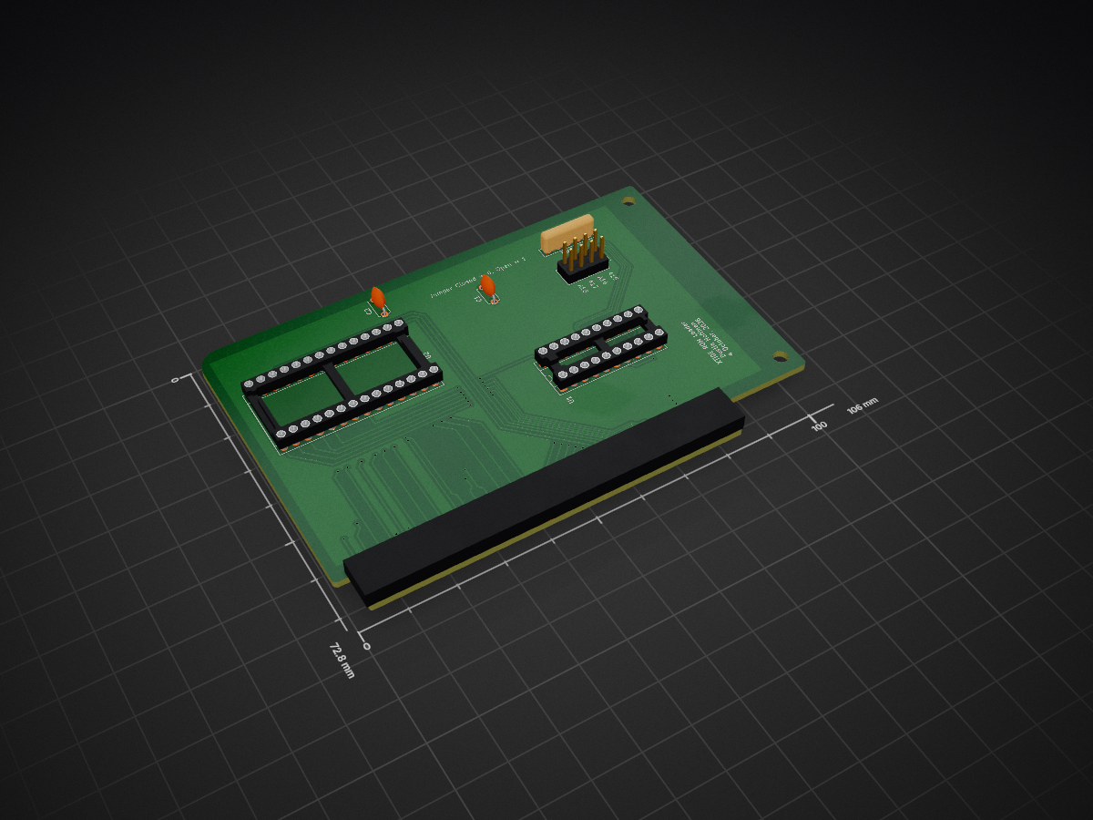
An 8-bit ISA card that holds a 27C256 EPROM as an option ROM in the upper memory area of a PC/XT-class machine, typically to load the XTIDE Universal BIOS.
XTIDE ROM Card is an open-source printed circuit board by hoffman373, from the hoffman373/XTIDE-ROM-Card repository on GitHub. It is a 2-layer board of 106 × 72.8 mm with 9 parts on 64 nets, routed with 294 tracks and 39 vias.
It is built around the 27C256-17/J. Its parts include 2 capacitors, 2 ICs and 2 connectors.
An 8-bit ISA card that holds a 27C256 EPROM as an option ROM in the upper memory area of a PC/XT-class machine, typically to load the XTIDE Universal BIOS.
The schematic is a redraw of Dan Hoover's "The $4 XTIDE" concept.
Bus_ISA_8bit)The 74LS688 compares A19-A15 against the levels set on J1. It also requires AEN low (no DMA cycle) and /MEMR low (memory read). When everything matches, it pulls ROM_SEL low and the EPROM drives D0-D7 for the read.
A19 is tied to match 1, so the 32 KB window always falls between 80000h and FFFFFh. RN1 pulls SEL_A15 to SEL_A18 high. Installing a jumper pulls that bit low.
| J1 pins | Address bit |
|---|---|
| 1-2 | A15 |
| 3-4 | A16 |
| 5-6 | A17 |
| 7-8 | A18 |
Jumper in = 0, jumper out = 1.
| ROM base | A18 | A17 | A16 | A15 | Jumpers installed |
|---|---|---|---|---|---|
| C8000h | 1 | 0 | 0 | 1 | 3-4, 5-6 |
| D0000h | 1 | 0 | 1 | 0 | 1-2, 5-6 |
| D8000h | 1 | 0 | 1 | 1 | 5-6 |
| E0000h | 1 | 1 | 0 | 0 | 1-2, 3-4 |
| E8000h | 1 | 1 | 0 | 1 | 3-4 |
git clone https://github.com/hoffman373/XTIDE-ROM-Card.gitxtide_rom_card.kicad_pro.Custom footprints live in lib/footprints/ and are registered through the project's fp-lib-table using ${KIPRJMOD}, so no library setup is needed. Everything else uses stock KiCad symbols and footprints.
Burn the ROM image (for example, an XTIDE Universal BIOS build configured for your controller) to a 27C256 with any EPROM programmer. If the image is smaller than 32 KB, pad it to 32 KB with FFh. The BIOS checksum must be valid or the system BIOS will skip the ROM during its option ROM scan.
CC BY-SA 4.0, share-alike with the original $4 XTIDE design.
| Qty | Value | Footprint | References |
|---|---|---|---|
| 2 | 100nF | Capacitor_THT:C_Disc_D5.0mm_W2.5mm_P5.00mm | C1, C2 |
| 2 | MountingHole | MountingHole:MountingHole_3.2mm_M3 | H1, H2 |
| 1 | 27C256 | Package_DIP:DIP-28_W15.24mm_Socket | U2 |
| 1 | 74LS688 | Package_DIP:DIP-20_W7.62mm_Socket | U1 |
| 1 | Bus_ISA_8bit | myproject:PC_AT_8BIT | J3 |
| 1 | Conn_02x04_Odd_Even | Connector_PinHeader_2.54mm:PinHeader_2x04_P2.54mm_Vertical | J1 |
| 1 | R_Network04_US | Resistor_THT:R_Array_SIP5 | RN1 |
monotech/NuXT
MicroATX Turbo XT Motherboard, with VGA, Floppy, CF, Serial


hkzlab/CGA_Redux
The Color Graphics Adapter Redux board is a more or less faithful clone of the original IBM CGA, based on the original schematics


tebl/C64-Kernal-Switcher
Switchless kernal switcher for the common breadbin Commodore 64, "longboards". Reuses power LED for easier use.
It measures 106 × 72.8 mm and has 2 copper layers, 1.6 mm thick.
9 parts, built around the 27C256-17/J. The full list of its parts is on this page, with links to each part's symbol and footprint where PCBKit's library has them.
From the hoffman373/XTIDE-ROM-Card repository on GitHub, at the commit this page was made from: the board is xtide_rom_card.kicad_pcb and its schematic xtide_rom_card.kicad_sch. PCBKit opens the board in the browser, with nothing to install.
Its repository states no licence, so its author keeps all rights: ask hoffman373 before reusing the design.