
2 layers96.8 × 97 mm
Psoc5power
profdc9/DRSSTC-PCB-Pack
A pack of PCBs for a dual resonant solid state tesla coil setup. Pretty much everything you need.
133 parts59

 hkzlab/EGA-2-RGBS7
EPROM based EGA/CGA to analog RGBS converter
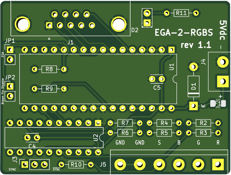
EGA2RGBC is an open-source printed circuit board by hkzlab, from the hkzlab/EGA-2-RGBS repository on GitHub, published under the CC-BY-SA-4.0 licence. It is a 2-layer board of 59.7 × 45.1 mm with 27 parts on 35 nets, routed with 382 tracks and 0 vias.
It is built around the 1N4733A. Its parts include 10 resistors, 5 capacitors, 4 connectors, 2 ICs and 2 diodes. It belongs with the retro computing and games and lEDs and displays boards of this library.
Months ago I ran into this video on YouTube that described how to implement an EGA/CGA to analog RGBS signal using just a ROM and a few passive components. Thinking it was a nice idea, I decided to implement my variant of it (including the tool that generates the values to program the EPROM), also including an optional buffer on the outputs of the ROM.
CAVEAT EMPTOR: For now I tested this board only in DOS with a CGA card. Will update this note when I test EGA and colours.
Note that this will not convert EGA/CGA to VGA, it will just make the signal analog and compatible with either a SCART input or a scaler like the GBS8200 (tested with gbs-control firmware).
Remember to program the EPROM with the bin file provided in the repository.
You can omit the following components:
Omit F1 and D1, bridge the two connections points of F1. Do this if you trust your power supply and yourself not to make shorts.
You can also omit the power indicator led D2 and its resistor R11
You can omit both U1 and U2 sockets. Remember to mount C4, C5, R8 and R9 on the underside of the board if you do this.
You can omit U2 entirely. Just bridge the following points on the footprint:
Also omit C4 in this case.
| Qty | Value | Footprint | References |
|---|---|---|---|
| 4 | 470 | Resistor_THT:R_Axial_DIN0204_L3.6mm_D1.6mm_P7.62mm_Horizontal | R2, R4, R6, R10 |
| 3 | 22pF | Capacitor_THT:C_Disc_D3.0mm_W2.0mm_P2.50mm | C1, C2, C3 |
| 3 | 680 | Resistor_THT:R_Axial_DIN0204_L3.6mm_D1.6mm_P7.62mm_Horizontal | R3, R5, R7 |
| 2 | 100nF | Capacitor_THT:C_Disc_D3.0mm_W2.0mm_P2.50mm | C4, C5 |
| 2 | 4.7k | Resistor_THT:R_Axial_DIN0204_L3.6mm_D1.6mm_P7.62mm_Horizontal | R8, R9 |
| 1 | 10k | Resistor_THT:R_Array_SIP9 | RN1 |
| 1 | 1N4733A | Diode_THT:D_DO-41_SOD81_P10.16mm_Horizontal | D1 |
| 1 | 1k | Resistor_THT:R_Axial_DIN0204_L3.6mm_D1.6mm_P7.62mm_Horizontal | R11 |
| 1 | 250mA | Fuse:Fuse_1206_3216Metric | F1 |
| 1 | 27C010 | Package_DIP:DIP-32_W15.24mm | U1 |
| 1 | 74LS244 | Package_DIP:DIP-20_W7.62mm | U2 |
| 1 | Brown Fix | Connector_PinHeader_2.54mm:PinHeader_1x02_P2.54mm_Vertical | JP2 |
| 1 | CSync Selection | Connector_PinSocket_2.54mm:PinSocket_1x03_P2.54mm_Vertical | J3 |
| 1 | EGA Input | Connector_Dsub:DSUB-9_Female_Horizontal_P2.77x2.84mm_EdgePinOffset4.94mm_Housed_MountingHolesOffset7.48mm | J1 |
| 1 | EGA/CGA | Connector_PinHeader_2.54mm:PinHeader_1x02_P2.54mm_Vertical | JP1 |
| 1 | Power | TerminalBlock:TerminalBlock_bornier-2_P5.08mm | J4 |
| 1 | Power | LED_THT:LED_D2.0mm_W4.8mm_H2.5mm_FlatTop | D2 |
| 1 | Video Out | TerminalBlock:TerminalBlock_bornier-6_P5.08mm | J5 |
profdc9/DRSSTC-PCB-Pack
A pack of PCBs for a dual resonant solid state tesla coil setup. Pretty much everything you need.


robsonsmartins/usbflashprog
A memory device programmer (Flash/EPROM/E2PROM) board and software, connected to PC by USB port.


ToneAlchemy/BiasPro
A professional-grade, dual-probe Arduino Bias Meter for guitar tube amplifiers. Open source hardware & firmware

profdc9/LinearPS
Linear constant constant/current constant voltage power supply PCB

Starsurfer78/TeensyMower-PCBs
PCB's Folder for Teensy 4.1 based Robot Lawn Mower

It measures 59.7 × 45.1 mm and has 2 copper layers, 1.6 mm thick.
27 parts, built around the 1N4733A. The full list of its parts is on this page, with links to each part's symbol and footprint where PCBKit's library has them.
From the hkzlab/EGA-2-RGBS repository on GitHub, at the commit this page was made from: the board is EGA2RGBC_EPROM/EGA2RGBC.kicad_pcb. PCBKit opens the board in the browser, with nothing to install.
Its repository publishes it under the CC-BY-SA-4.0 licence: you may reuse it on that licence's terms (keep the author's notice, and for a copyleft licence share your changes alike).