
2 layers178 × 145 mm
Ultra DB X51 v1
ExploreEmbedded/8051_DevelopmentBoard
Design files and sample code for 8051 development Ultra Boards
145 parts70

 hjf/video-isolator1
A video isolation circuit for adding inputs such as Y/C (S-Video) to hot-chassis TVs, including the Sony KV-1484, KV-2184, and KV-1442.
Video isolator is an open-source printed circuit board by hjf, from the hjf/video-isolator repository on GitHub. It is a 2-layer board of 63.5 × 15.4 mm with 23 parts on 19 nets, routed with 91 tracks and 0 vias.
It is built around the BC548. Its parts include 10 resistors, 4 capacitors, 4 transistors, 2 connectors and 1 IC. It belongs with the interfaces and adapters boards of this library.
A video isolation circuit for adding inputs such as Y/C (S-Video) to hot-chassis TVs, including the Sony KV-1484, KV-2184, and KV-1442.
The primary use is adding a chroma (C) input to a TV that already has an isolated composite video input. Luma (Y) uses the existing video input path.
This modification is intended for people experienced in servicing hot-chassis TVs. A mistake can cause a fatal electric shock or damage connected equipment, including a console.
These notes describe the original modification, not a complete installation or safety procedure. Wiring and supply rails must be verified for the specific TV.
Do not connect the isolated and non-isolated grounds together. Incorrect power or ground connections can defeat isolation without any obvious sign of damage.
The TV models above were sold with and without AV inputs. This project primarily targets versions with AV inputs. A version without AV inputs may require one isolator for composite video or two for Y/C, plus an isolated power supply for the isolated side.
The circuit is based on the application circuit on page 10 of the HCPL-4562 datasheet. A local copy of the datasheet is included in case the external link becomes unavailable.
Open video-isolator.kicad_pro in KiCad. The design files were saved with KiCad 8.
| File | Purpose |
|---|---|
| video-isolator.kicad_pro | Project settings |
| video-isolator.kicad_sch | Schematic |
| video-isolator.kicad_pcb | PCB layout |
| ltspice/ | Simulation schematic, optoisolator symbol, and model |
The example board uses YCM301/YCM302 in the Y/C splitter and comb-filter circuitry. The original modification lifts pin 1 of the comb filter and injects the isolator output there, feeding chroma directly from the Y/C input. Luma continues through the normal video path.
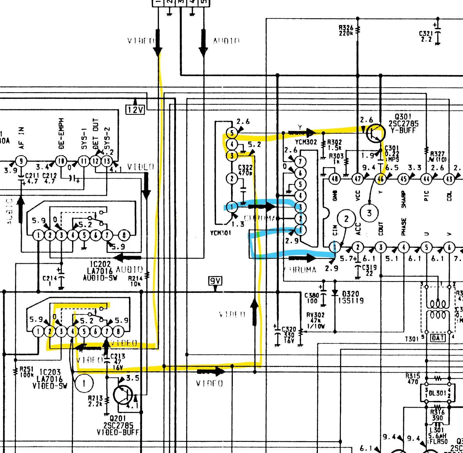
The chroma input may need a voltage divider or termination. Use capacitive coupling, with the termination before the series capacitor: the example schematic shows the chroma input biased at approximately 3 V. Excessive chroma level can cause artifacts.
Identify the input board's isolated and non-isolated supply and ground rails before connecting the circuit. Keep each side of the isolator connected to its corresponding supply and ground.
In the original installation, the RCA input ground identifies the isolated side, while chassis ground identifies the non-isolated side. The input board's small transformer and associated smoothing capacitor help locate the isolated supply. Verify the actual connections and supply voltages against the TV's schematic.
The onboard potentiometer adjusts the amplifier's bias, not its gain. Adjust it so the amplifier operates in its linear region. Too much bias can cause overheating; too little can cause nonlinearity.
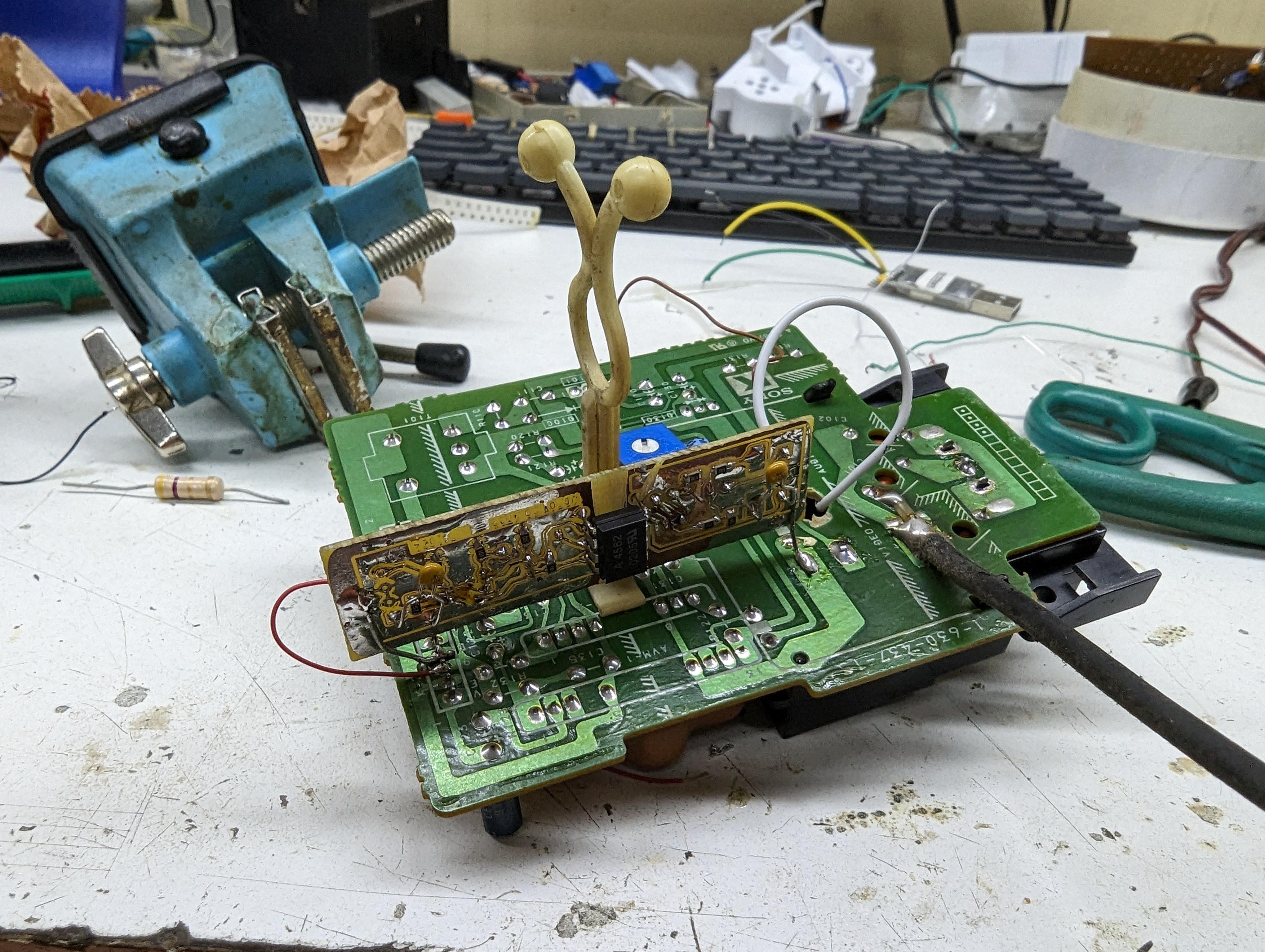
The isolator mounted on the TV's input board:
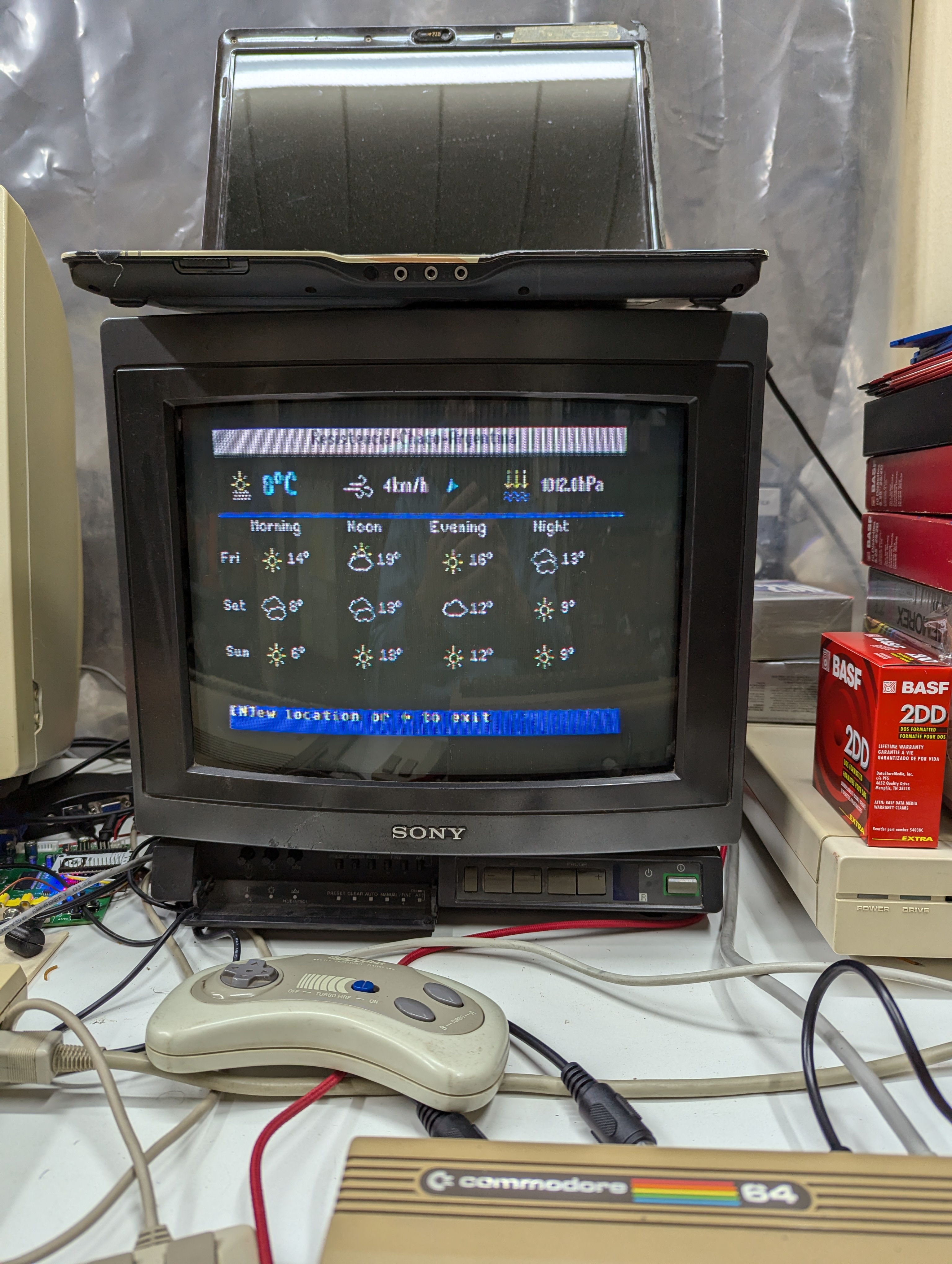
The modified TV displaying a picture:
A small timing mismatch was observed after the modification. Chroma bypasses part of the original processing path while luma still passes through the Y/C circuitry. In the example below, the mouse cursor's chroma appears ahead of its luma, producing a blue shadow.
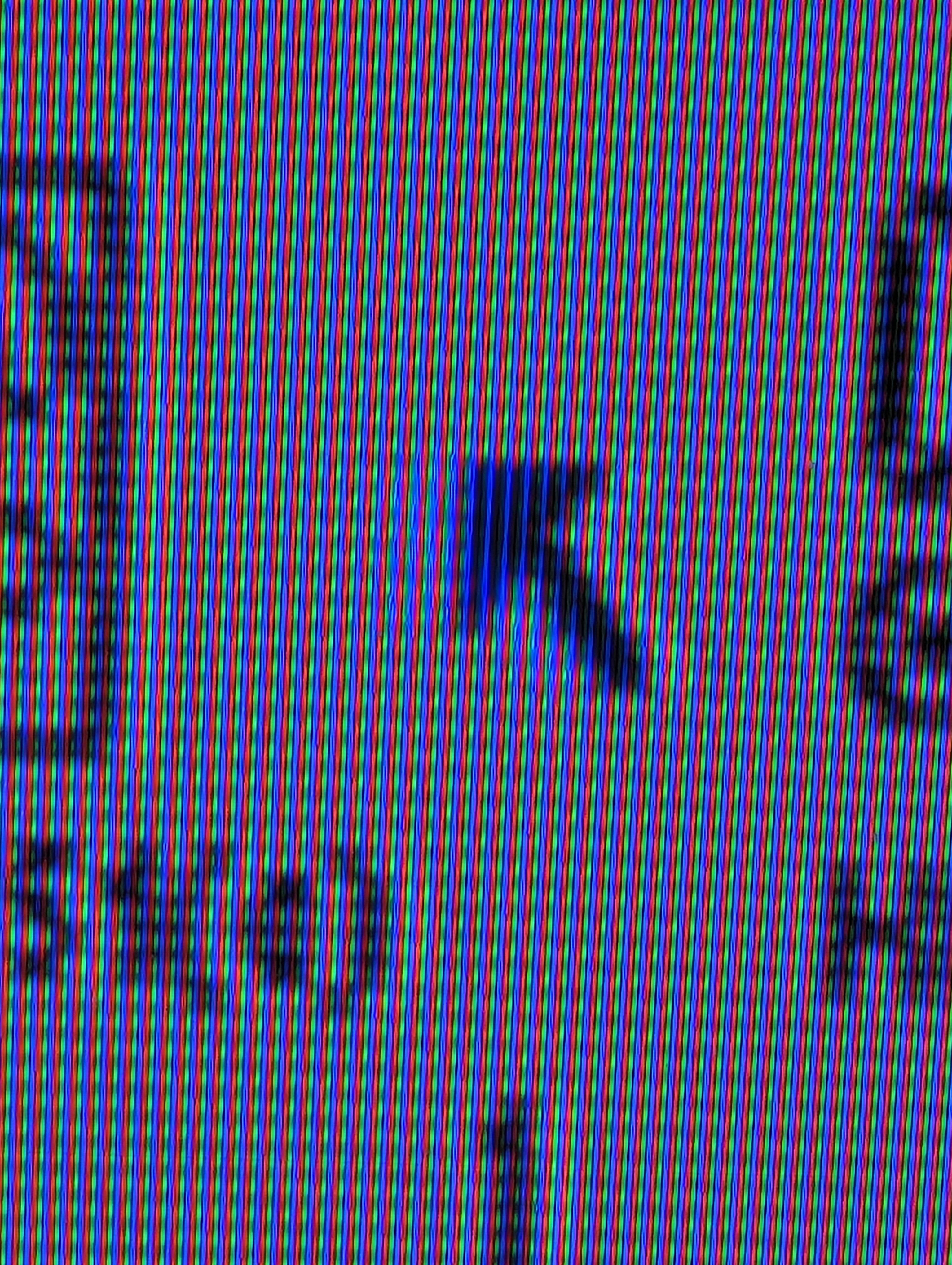
The effect is subtle and most noticeable under extreme conditions. Bypassing the Y/C filtering entirely was suggested as a possible fix, but has not been tested.
| Qty | Value | Footprint | References |
|---|---|---|---|
| 4 | BC548 | Package_TO_SOT_THT:TO-92_HandSolder | Q1, Q2, Q3, Q4 |
| 3 | C | Capacitor_SMD:C_0805_2012Metric_Pad1.18x1.45mm_HandSolder | C2, C5, C6 |
| 2 | 100 | Resistor_SMD:R_0805_2012Metric_Pad1.20x1.40mm_HandSolder | R3, R10 |
| 2 | Conn_01x04_Socket | Connector_PinSocket_2.54mm:PinSocket_1x04_P2.54mm_Vertical | J1, J2 |
| 1 | 1000 | Resistor_SMD:R_0805_2012Metric_Pad1.20x1.40mm_HandSolder | R2 |
| 1 | 15k | Resistor_THT:R_Axial_DIN0204_L3.6mm_D1.6mm_P7.62mm_Horizontal | R7 |
| 1 | 1k | Resistor_SMD:R_0805_2012Metric_Pad1.20x1.40mm_HandSolder | R8 |
| 1 | 470 * | Resistor_SMD:R_0805_2012Metric_Pad1.20x1.40mm_HandSolder | R11 |
| 1 | 51 | Resistor_SMD:R_0805_2012Metric_Pad1.20x1.40mm_HandSolder | R4 |
| 1 | 6800 | Resistor_SMD:R_0805_2012Metric_Pad1.20x1.40mm_HandSolder | R1 |
| 1 | 6N136 | Package_DIP:DIP-8_W7.62mm | U1 |
| 1 | 750 | Resistor_SMD:R_0805_2012Metric_Pad1.20x1.40mm_HandSolder | R9 |
| 1 | 9.1k | Resistor_SMD:R_0805_2012Metric_Pad1.20x1.40mm_HandSolder | R6 |
| 1 | C_Polarized | Capacitor_THT:CP_Radial_D6.3mm_P2.50mm | C1 |
| 1 | D | Diode_SMD:D_MELF-RM10_Universal_Handsoldering | D1 |
| 1 | R_Potentiometer | Potentiometer_THT:Potentiometer_Bourns_3266Y_Vertical | RV1 |
ExploreEmbedded/8051_DevelopmentBoard
Design files and sample code for 8051 development Ultra Boards


DarcyJProjects/touchtone555
An open-source DIY, NE555-based analogue synthesizer - play notes with a stylus


clemarfolly/Microdigital-TK2000
Reprodução da PCB do TK-2000 da Microdigital, clone do Micro-Professor MPF-II

Danjovic/Soda-IDE
8 bit Compact Flash Interface for MSX computers

alvaroalea/all-spectrum-clones
Schematic of a 8bit computer, clone of Sinclair ZX Spectrum
It measures 63.5 × 15.4 mm and has 2 copper layers, 1.6 mm thick.
23 parts, built around the BC548. The full list of its parts is on this page, with links to each part's symbol and footprint where PCBKit's library has them.
From the hjf/video-isolator repository on GitHub, at the commit this page was made from: the board is kicad/video-isolator.kicad_pcb and its schematic kicad/video-isolator.kicad_sch. PCBKit opens the board in the browser, with nothing to install.
Its repository states no licence, so its author keeps all rights: ask hjf before reusing the design.