
2 layers99.6 × 99.8 mm

 aliqut/3xosc40
3xOsc | 3 VCO Eurorack Module
3xosc is an open-source printed circuit board by aliqut, from the aliqut/3xosc repository on GitHub, published under the GPL-3.0 licence. It is a 4-layer board of 99.6 × 99.8 mm with 92 parts on 100 nets, routed with 683 tracks and 48 vias.
It is built around the BC548 and BC558. Its parts include 52 resistors, 10 capacitors, 6 transistors, 5 diodes and 4 ICs. It belongs with the audio and music boards of this library.
3xOsc | 3 VCO Eurorack Module
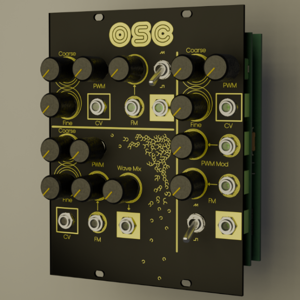
This is a Eurorack format VCO synth module, based on Moritz Klein's VCO design.
The module was designed using KiCad.
Features:
Each of the 3 oscillators has:
Controls unique to each oscillator:
BOM.csv file. (If you have made any changes to the schematics, it is best to regenerate the BOMs).Once you have your PCBs and components, refer to the BOM and schematic to solder the components onto the board.
The module is split into three boards, the main board, the connector board, and the front panel. You can make your own front panel if you'd prefer.
The front panel board has no electrical connections and is purely aesthetic. I recommend letting your PCB manufacturer know this to avoid any issues.
The main and connector board are connected via the pin headers on the top and bottom of the PCBs, make sure you orient the pin headers properly before soldering. The front panel is secured onto the connector board using hex nuts.
To view the front panel on KiCad, you need to install the fonts in the fonts/ folder from this repo, or replace them with your font of choice.
To get the shiny gold finish for the exposed copper used for text/graphics, make sure you get your PCB manufactured with an ENIG finish. Most PCB manufacturers offer this as an option.
I went for a black solder mask, but you get the option to choose from many different colours when ordering your PCB.
Pull requests are the best way to propose changes to the schematics.
master.In short, when you submit code changes, your submissions are understood to be under the same GPL license that covers the project.
I use GitHub issues to track public bugs. Report a bug by opening a new issue.
Issue Reports tend to have:
| Qty | Value | Footprint | References |
|---|---|---|---|
| 14 | 100K | Resistor_THT:R_Axial_DIN0309_L9.0mm_D3.2mm_P12.70mm_Horizontal | R1, R4, R5, R7, R11, R13, R16, R20, R34, R37, R39, R41, R43, R46 |
| 9 | 100k | Resistor_THT:R_Axial_DIN0309_L9.0mm_D3.2mm_P12.70mm_Horizontal | R17, R21, R22, R25, R27, R28, R30, R32, R47 |
| 9 | 10K | Resistor_THT:R_Axial_DIN0204_L3.6mm_D1.6mm_P2.54mm_Vertical | TH1, TH2, TH3, TH5, TH6, TH8, TH9, TH10, TH12 |
| 6 | 1M | Resistor_THT:R_Axial_DIN0207_L6.3mm_D2.5mm_P7.62mm_Horizontal | R6, R8, R12, R14, R38, R40 |
| 5 | 1uF | Capacitor_THT:C_Disc_D3.0mm_W1.6mm_P2.50mm | C3, C4, C5, C6, C8 |
| 5 | D | Diode_THT:D_DO-15_P5.08mm_Vertical_AnodeUp | D1, D2, D3, D4, D5 |
| 4 | 20k | Resistor_THT:R_Axial_DIN0207_L6.3mm_D2.5mm_P7.62mm_Horizontal | R24, R26, R29, R31 |
| 3 | 10k | Resistor_THT:R_Axial_DIN0204_L3.6mm_D1.6mm_P2.54mm_Vertical | TH4, TH7, TH11 |
| 3 | 1K | Potentiometer_THT:Potentiometer_Bourns_3006Y_Horizontal | R3, R10, R36 |
| 3 | 1K5 | Resistor_THT:R_Axial_DIN0207_L6.3mm_D2.5mm_P10.16mm_Horizontal | R2, R9, R35 |
| 3 | 2.2nF | Capacitor_THT:C_Disc_D4.7mm_W2.5mm_P5.00mm | C1, C2, C7 |
| 3 | 33k | Resistor_THT:R_Axial_DIN0207_L6.3mm_D2.5mm_P10.16mm_Horizontal | R18, R23, R45 |
| 3 | BC548 | Package_TO_SOT_THT:TO-92_Inline | Q2, Q4, Q6 |
| 3 | BC558 | Package_TO_SOT_THT:TO-92_Inline | Q1, Q3, Q5 |
| 3 | TL074 | Package_DIP:DIP-14_W7.62mm_Socket | U2, U3, U4 |
| 2 | 10R | Resistor_THT:R_Axial_DIN0207_L6.3mm_D2.5mm_P10.16mm_Horizontal | R51, R52 |
| 2 | 10uF | Capacitor_THT:CP_Radial_D5.0mm_P2.00mm | C9, C10 |
| 2 | 1K | Resistor_THT:R_Axial_DIN0207_L6.3mm_D2.5mm_P10.16mm_Horizontal | R49, R50 |
| 2 | 200k | Resistor_THT:R_Axial_DIN0207_L6.3mm_D2.5mm_P10.16mm_Horizontal | R15, R19 |
| 2 | 68K | Resistor_THT:R_Axial_DIN0207_L6.3mm_D2.5mm_P10.16mm_Horizontal | R42, R48 |
| 2 | Conn_01x32_Socket | Connector_PinHeader_2.54mm:PinHeader_1x32_P2.54mm_Vertical | J1, J3 |
| 1 | 14K | Resistor_THT:R_Axial_DIN0207_L6.3mm_D2.5mm_P10.16mm_Horizontal | R44 |
| 1 | 20K | Resistor_THT:R_Axial_DIN0207_L6.3mm_D2.5mm_P7.62mm_Horizontal | R33 |
| 1 | 40106 | Package_DIP:DIP-14_W7.62mm_Socket | U1 |
| 1 | Conn_02x05_Odd_Even | Connector_PinHeader_2.54mm:PinHeader_2x05_P2.54mm_Vertical | J2 |


wilsondr9999/1005-Flash-Programmer
Flash Programmer for SST39 Flash ROMs


loowiz/EDA_LabPS
This is a power supply project based on the chinese DIY kit "0-30V 2mA-3A Adjustable DC Regulated Power Supply".
It measures 99.6 × 99.8 mm and has 4 copper layers, 1.6 mm thick.
92 parts, built around the BC548 and BC558. The full list of its parts is on this page, with links to each part's symbol and footprint where PCBKit's library has them.
From the aliqut/3xosc repository on GitHub, at the commit this page was made from: the board is KiCad/Main/MAIN.kicad_pcb and its schematic KiCad/Connector/CONNECTOR.kicad_sch. PCBKit opens the board in the browser, with nothing to install.
Its repository publishes it under the GPL-3.0 licence: you may reuse it on that licence's terms (keep the author's notice, and for a copyleft licence share your changes alike).