


6 layers304.8 × 243.8 mm
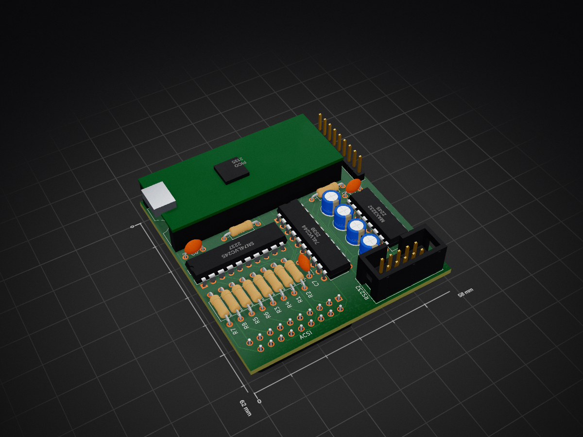
Hardware for file transfer and serial communication between PC and Atari 16/32 bit computers.
Sthd is an open-source printed circuit board by hildenborg, from the hildenborg/atari-link repository on GitHub, published under the MIT licence. It is a 2-layer board of 58 × 62 mm with 24 parts on 74 nets, routed with 352 tracks and 0 vias.
It is built around the 74LVC244, MAX3232ID and SN74LVC245AN. Its parts include 10 resistors, 7 capacitors, 4 ICs and 3 connectors. It belongs with the RP2040 boards of this library.
The purpose of Atari-Link is to give developers using m68k-atari-dev toolchain the possibillity of developing for real Atari computers the same way they are used to target the Hatari emulator.
If you aren't a developer and only want a ACSI SD-Card hard disk emulator, then there are many other options with better support.
The wiki is recommended for deeper information
The hardware is designed in KiCad and the project can be found in the "kicad" directory.
It is designed to be "easy" to build by hand, and the wiki have more information about that.
The hardware is based around the Raspberry Pico and the formware source is in the "firmware" directory.
The project is dependent on a submodule, so do not forget to do git submodule init and git submodule update after cloning this git repository.
If you have built the hardware, and just want to get going, then download atari-link.zip and extract its contents.
Flash the Pico with "atari_link.uf2" and put "config.txt, "tos32mb_ahdi5_boot.img" and "tos32mb_gdbsrv.img" on a FAT32 formatted SD-card.
This will set you up with a development system that should work on pretty much anything Atari have made.
You may need to edit the "config.txt" file if you have other hard drives connected, so there aren't any device id collision.
The hard disk images in the release is TOS 32MB formatted images so they should work on just about anything.
The "config.txt" in the release is set up so the "tos32mb_ahdi5_boot.img" disk image is not seen by the PC and the "tos32mb_gdbsrv.img" is read-only by the Atari. The "tos32mb_gdbsrv.img" is visible on the PC as a USB drive and files written to it are immediately accessible on the Atari.
NOTE: Even TOS formatted hard disk images are accessible to the PC as a USB drive. There's a wiki page that describes how it works.
The "extras" directory contains a "hello world" example using VsCode and Atari-Link with m68k-atari-dev toolchain.
This example works exactly the same as the "vscode_hatari" example in the m68k-atari-dev examples.
After having set up your Atari-Link with firmware and a SD-Card with the released images, you should now be able to start your atari and have a C and D drive (you may have to install the D drive).
The D drive is the drive that appears as a USB drive on your PC. This is specified in the "config.txt" file that came with the disk images.
On the D drive there is "gdbsrv.ttp" which you start with "--multi hello.prg" arguments.
On your PC, execute "./vscode.sh" and in VsCode, press "Shoft-Ctrl-B" to build and "F5" to execute on your atari.
This project is MIT licensed.
The submodule: no-OS-FatFS-SD-SPI-RPi-Pico is a separate project and is Apache-2.0 licensed.
| Qty | Value | Footprint | References |
|---|---|---|---|
| 8 | 47R | Resistor_THT:R_Axial_DIN0207_L6.3mm_D2.5mm_P10.16mm_Horizontal | R1, R2, R3, R4, R5, R6, R7, R8 |
| 4 | 0.1uF | Capacitor_THT:CP_Radial_D5.0mm_P2.00mm | C1, C2, C3, C4 |
| 3 | 1uF | Capacitor_THT:C_Disc_D5.0mm_W2.5mm_P5.00mm | C5, C6, C7 |
| 2 | 10K | Resistor_THT:R_Axial_DIN0207_L6.3mm_D2.5mm_P10.16mm_Horizontal | R9, R10 |
| 1 | 74LVC244 | Package_DIP:DIP-20_W7.62mm | U5 |
| 1 | ACSI | ProjectLib:DB19 | J1 |
| 1 | MAX3232 | Package_DIP:DIP-16_W7.62mm | U1 |
| 1 | Pico | ProjectLib:Pico | U4 |
| 1 | RS232 | Connector_IDC:IDC-Header_2x05_P2.54mm_Vertical | J2 |
| 1 | SD Mod | Connector_PinHeader_2.54mm:PinHeader_1x09_P2.54mm_Vertical | J3 |
| 1 | SN74LVC245 | Package_DIP:DIP-20_W7.62mm | U2 |
It measures 58 × 62 mm and has 2 copper layers, 1.6 mm thick.
24 parts, built around the 74LVC244, MAX3232ID and SN74LVC245AN. The full list of its parts is on this page, with links to each part's symbol and footprint where PCBKit's library has them.
From the hildenborg/atari-link repository on GitHub, at the commit this page was made from: the board is kicad/sthd.kicad_pcb and its schematic kicad/sthd.kicad_sch. PCBKit opens the board in the browser, with nothing to install.
Its repository publishes it under the MIT licence: you may reuse it on that licence's terms (keep the author's notice, and for a copyleft licence share your changes alike).


cartheur/M6809-multicomputer
Systems-matching the requirements of novel-ideal in metal to architecture


polpo/picogus
Emulation of ISA sound cards and CD-ROM on Raspberry Pi Pico (GUS, SB/Adlib, MPU-401, Tandy, CMS, Panasonic CD-ROM) with USB mouse/joystick support

robfinch/Cores
Cores ===== RTF's Cores Use at your own risk. Welcome to my galaxy of cores. Contained in the directories are IP cores, source code for digital circuits.