2 layers245.1 × 160 mm
8-Bit CPU 32k
slu4coder/Minimal-64x4-Home-Computer
My DIY TTL home computer with VGA and PS/2 and 4x the processing power of a Commodore C64 or Apple II.
139 parts326

 hharte/z80_ssd11
This project implements a solid-state disk controller for the Z80. The board plugs into the Z80 CPU socket and the Z80 CPU plugs into the board.
Z80 ssd is an open-source printed circuit board by hharte, from the hharte/z80_ssd repository on GitHub, published under the MIT licence. It is a 2-layer board of 42.5 × 90 mm with 22 parts on 50 nets, routed with 526 tracks and 29 vias.
It is built around the PIC18F47Q84-E/P and 74HC245D. Its parts include 6 capacitors, 4 connectors, 3 resistors, 3 ICs and 2 diodes. It belongs with the retro computing and games boards and the PIC boards of this library.


This project implements a solid-state disk controller for the Z80. The board plugs into the Z80 CPU socket and the Z80 CPU plugs into the board. A Microchip PIC18F47Q43 microcontroller implements the controller and SD Memory card interface using SPI.
While the z80_ssd could implement almost any hard disk controller that uses I/O ports for data transfer, the particular controller implemented mimics the IBC/Integrated Business Computers MCC Hard Disk Controller.
The original controller supports four ST-506 drives. Drive 0 is the boot drive, and Drive 3 is a 5- or 10MB removable cartridge drive. The other two drives were unused in the standard IBC MultiStar computer.
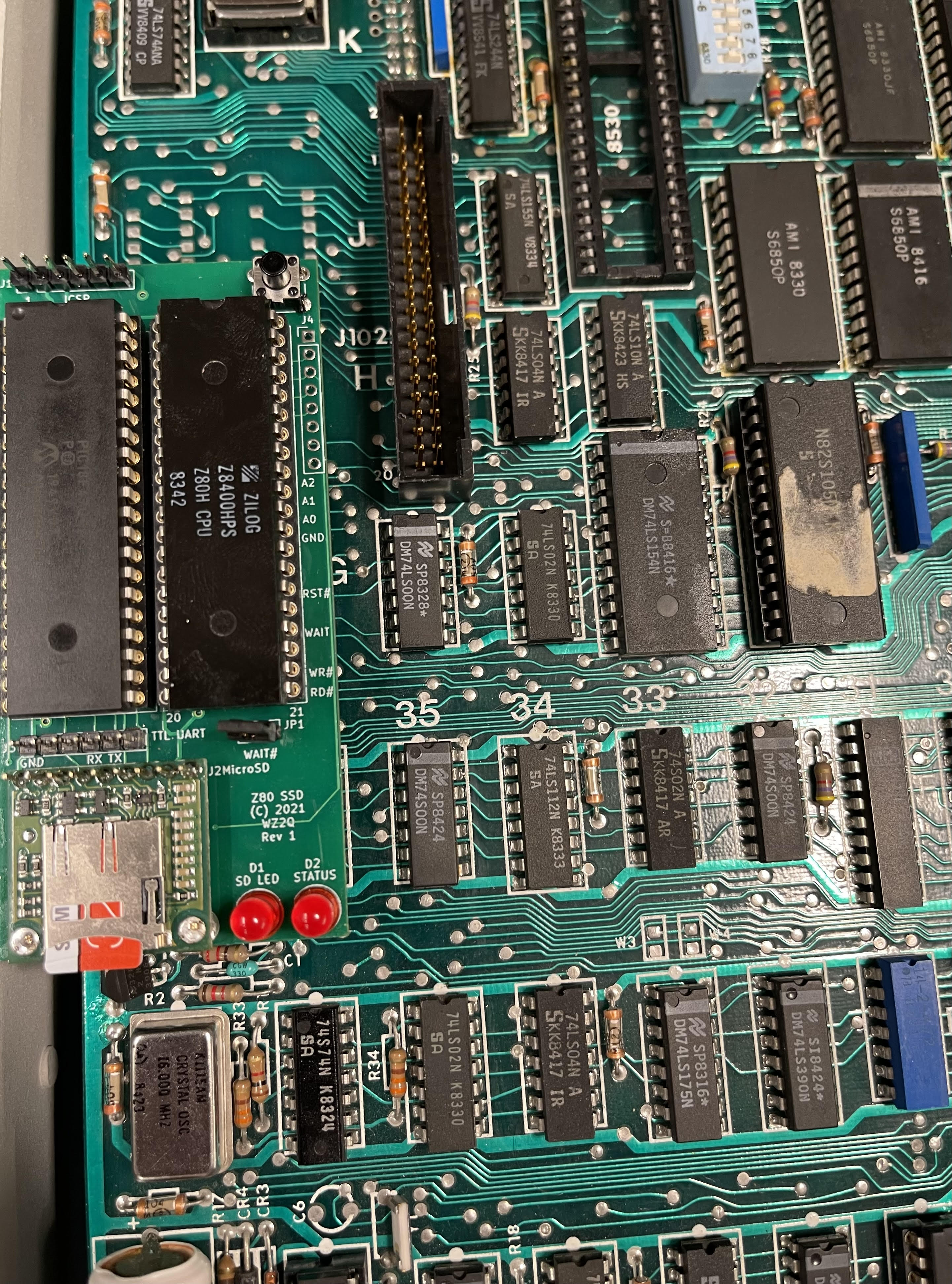
The z80_ssd piggybacks on the Z80 CPU socket to gain access to all of the Z80 CPU’s signals. The PIC18F47Q43 was chosen because it has a relatively large amount of RAM (8K) and FLASH (128K.) To minimize the number of components required, and to facilitate maximum flexibility, the MCU’s Configurable Logic Cells (CLCs) are used:
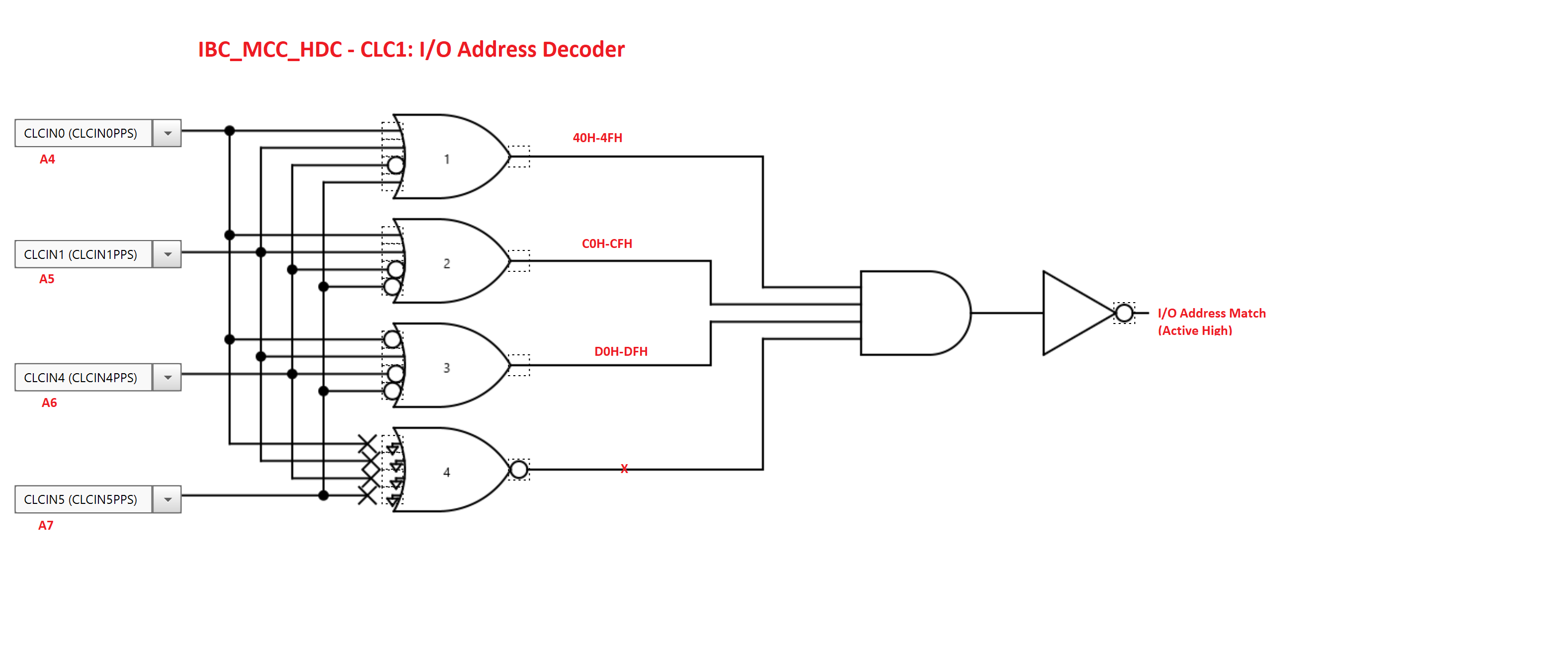
CLC1 - Decodes CPU_A[7:4] to allow the z80_ssd to respond to a block of 16 I/O addresses. The current design uses one 4-input AND gate to decode address 40h-4Fh, like the original disk controller. There are three spare 4-input AND gates in CLC1, so the design could be expanded to decode up to four blocks of 16 I/O ports if desired.
This schematic diagram illustrates three address ranges decoded by the z80_ssd: 40h-4Fh, 0C0h-0CFh, 0D0h-0DFh.
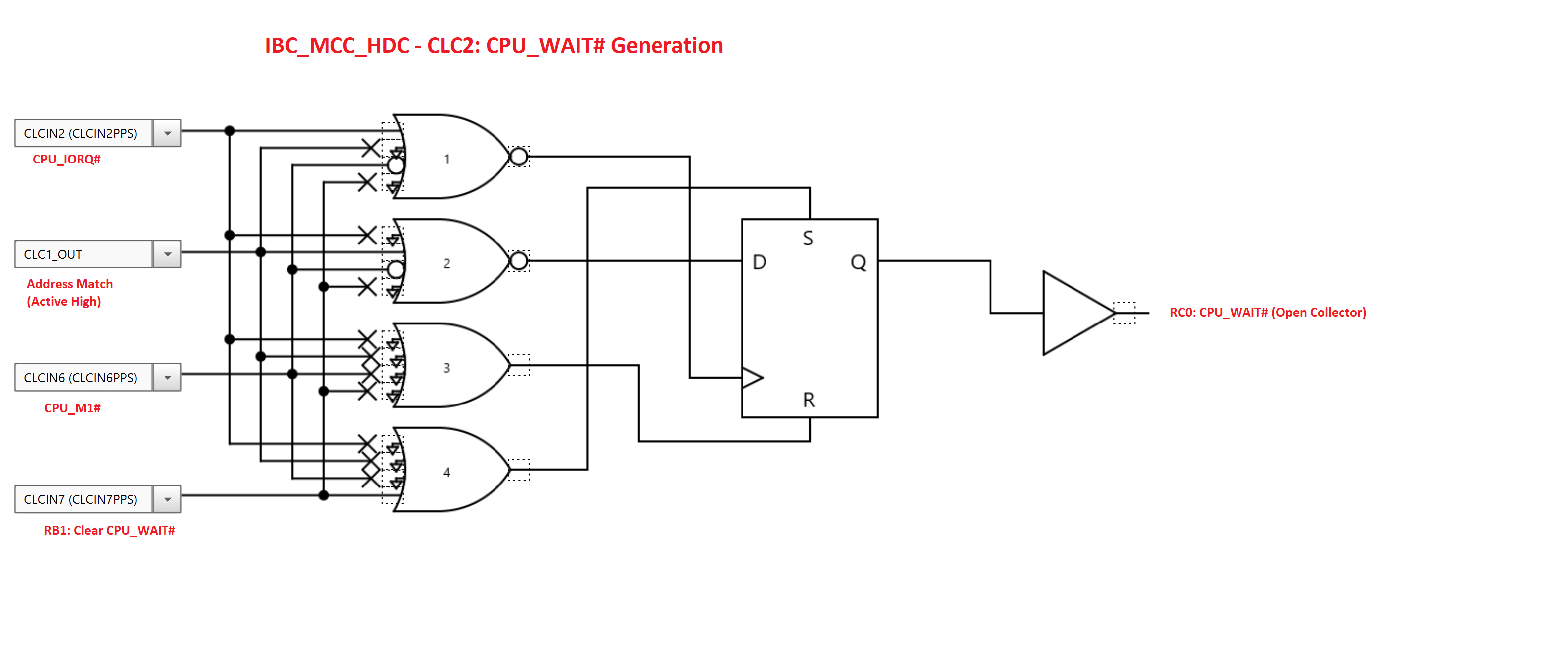
CLC2 - Uses the output of CLC1 along with CPU_M1# and CPU_IORQ# to set a flip-flop when the requested I/O access is performed by the CPU. The output of this flip-flop pulls down the CPU_WAIT# pin via an open-collector output from the MCU. CLC2 generates an interrupt to the MCU, and MCU then processes the I/O read or write. After the MCU finishes processing the I/O access, it de-asserts WAIT# by resetting the flip-flop in CLC2.
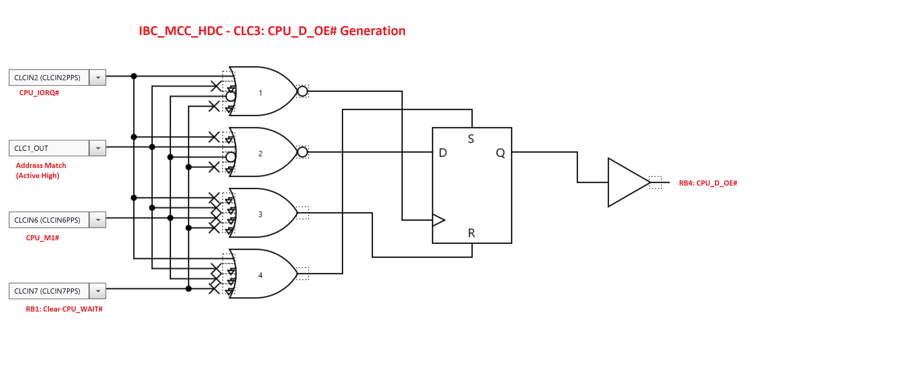
CLC3 - Although not strictly required, the z80_ssd employs a 74ABTH245 bus transceiver for the CPU data bus to ensure proper timing. The MCU’s CLC3 drives the bus transceiver’s output enable.
Due to the piggyback nature of the z80_ssd, it is fabricated on a 0.4mm thick PCB, and uses a machined Mill-Max long-pin DIP socket. To raise the z80_ssd above other components on the computer’s motherboard, the long-pin DIP is plugged into a stamped 40-pin DIP socket which is then inserted into the original Z80 CPU socket.
The SD memory card is connected to the MCU’s SPI interface. It uses the FatFs library and Microchip’s SD-SPI library. The activity LED on the z80_ssd is driven by the SD memory card’s CS# pin.
The SPI clock runs at 8MHz, and is in polled mode. It may be possible to increase the throughput by using interrupt-driven DMA mode, but I have not tried that.
Running OASIS 5.6, a 16MB disk partition can be verified (read) in 3 minutes, 35 seconds. While the I/O interface is much slower than the hardware-driven FIFO of the original disk controller design, the overall performance feels about the same: solid-state disks do not have seek or rotational latency overhead, which makes these aspects of the disk faster than the original.
>HDPERF

>SHOW TIME
05:33:00 Friday, October 22, 1993

>VERIFY S

Cylinder: 132 Head: 14

>SHOW TIME
05:36:33 Friday, October 22, 1993

D(8) Label: "REMOVBKU",
     Archived from disk "HOWARD1 " on 10/23/83 14:13,
     Capacity: 9,744K bytes (609-2-32),
     Available: 0K bytes (0%),
     Largest area: 0K bytes,
     1 file in use (out of 16).

S(3) Label: "HOWARD1 ",
     Archived to disk "REMOVBKU" on 10/23/83 14:13,
     Capacity: 15,960K bytes (133-15-32),
     Available: 14,884K bytes (93%),
     Largest area: 14,879K bytes,
188 files in use (out of 1,944).The z80_ssd includes a 5V TTL UART for console I/O as well as a standard Microchip ICSP port on a 1x6 0.1” header.
Jumper JP1 can be removed to block CPU_WAIT# from being asserted. This can be useful for debugging. JP1 should be installed for normal operation.
The z80_ssd hardware and MCU can be used to implement other types of I/O devices or different kinds of disk controllers. One thing to be aware of is that no other hardware in the system should drive the bus when the z80_ssd registers are accessed. For use in an S-100 bus system, additional logic would be needed to prevent the bus drivers on the S-100 board from driving against the z80_ssd. In the IBC MultiStar machine where I use the z80_ssd, I had to disable the on-board ST-506 controller. This was accomplished by removing the PAL that does the address decoding for the disk controller, tying one of the inputs inactive, and then placing the PAL back into the system.
| Qty | Value | Footprint | References |
|---|---|---|---|
| 5 | 0.1uF | Capacitor_SMD:C_0805_2012Metric | C1, C2, C3, C4, C5 |
| 2 | 470 | Resistor_SMD:R_0805_2012Metric | R2, R3 |
| 2 | Conn_01x06_Male | Connector_PinHeader_2.54mm:PinHeader_1x06_P2.54mm_Vertical | J1, J3 |
| 2 | LED | LED_THT:LED_D5.0mm | D1, D2 |
| 2 | MountingHole_Pad | MountingHole:MountingHole_2.2mm_M2_Pad | H1, H2 |
| 1 | 0.01uF | Capacitor_SMD:C_0805_2012Metric | C6 |
| 1 | 10K | Resistor_SMD:R_0805_2012Metric | R1 |
| 1 | 74HC245 | Package_SO:SSOP-20_4.4x6.5mm_P0.65mm | U3 |
| 1 | Conn_01x08_Male | Connector_PinHeader_2.54mm:PinHeader_1x08_P2.54mm_Vertical | J4 |
| 1 | Jumper | Connector_PinHeader_2.54mm:PinHeader_1x02_P2.54mm_Vertical | JP1 |
| 1 | PIC18F47Q84 | Package_DIP:DIP-40_W15.24mm_Socket | U2 |
| 1 | Pololu-2587_MicroSD | Connector_PinHeader_2.54mm:PinHeader_1x09_P2.54mm_Vertical | J2 |
| 1 | SW_Push | Button_Switch_THT:SW_PUSH_6mm | SW1 |
| 1 | Z80CPU | Package_DIP:DIP-40_W15.24mm_Socket | U1 |
slu4coder/Minimal-64x4-Home-Computer
My DIY TTL home computer with VGA and PS/2 and 4x the processing power of a Commodore C64 or Apple II.

slu4coder/Minimal-UART-Computer-1-2
Legacy: Version 1 and 2 of my TTL-only CPU featuring UART I/O, an expansion port, 512KB SSD at up to 10MHz clock speed

crmaykish/mackerel-68k
A series of single-board Motorola 68k computers with support for modern Linux

slu4coder/Minimal-64-Home-Computer
Legacy: Full TTL-only home computer with VGA and PS/2 and twice the processing power of a Commodore 64

Pixelvation/Pixelvation
This GitHub repository is the current home of Pixelvation and will be updated whenever there's some significant new development.

Board-Folk/MegaCD-Main-BD
Reproductions of main board PCBs for Sega's Mega CD/Sega CD add-on for the Mega Drive/Genesis console.


slu4coder/Minimal-UART-Computer-3
Version 3 of my educational DIY TTL computer built around a UART serial interface - now with blinkenlights!
It measures 42.5 × 90 mm and has 2 copper layers, 1.6 mm thick.
22 parts, built around the PIC18F47Q84-E/P and 74HC245D. The full list of its parts is on this page, with links to each part's symbol and footprint where PCBKit's library has them.
From the hharte/z80_ssd repository on GitHub, at the commit this page was made from: the board is hardware/z80_ssd.kicad_pcb. PCBKit opens the board in the browser, with nothing to install.
Its repository publishes it under the MIT licence: you may reuse it on that licence's terms (keep the author's notice, and for a copyleft licence share your changes alike).