
4 layers234 × 84 mm
Main panel
google/mozc-devices
Circuit diagrams and firmware source code for Gboard DIY keyboards
234 parts3kApache-2.0

 HexFud/HexKey60
Just a custom mechanical keyboard project designed by me
HexKey60 is an open-source printed circuit board by HexFud, from the HexFud/HexKey60 repository on GitHub. It is a 2-layer board of 321.8 × 112.3 mm with 206 parts on 173 nets, routed with 3,601 tracks and 467 vias.
It is built around the SK6812MINI-E. Its parts include 136 diodes, 68 switches and 1 connector. It belongs with the RP2040 boards of this library.
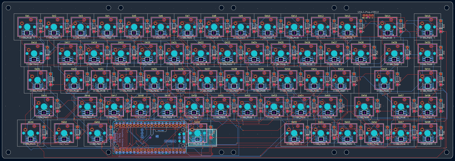
Just a custom mechanical keyboard project designed by me
Originally I was going for something more compact (Orpheus Pico, then XIAO RP2040, then RP2040-Zero) because the standard Pico seemed too bulky to fit between the switches. That problem went away once I moved the microcontroller under the spacebar, where there's way more free space, at that point the regular Pico made more sense, i had space to place it and it has enough pins to fit evry component.
Driven via PIO on GPIO21.
LED power comes straight from VBUS (5V), not from the Pico's 3.3V regulator, so the current spikes from 68 LEDs at once don't stress it. Max brightness needs to stay capped in firmware.
The Pico sits under the spacebar, away from the case edge where the connector needs to come out. D+/D- are hand-wired to test points TP2/TP3 on the back of the Pico (not routed through the PCB), going to a Treedix USB-C breakout mounted in the case. CC1/CC2 on the breakout already have pull-down resistors built in, so they're left unconnected.
The plate and the case are fully 3d printed
Live control from a PC over Raw HID (tastiera68_controller.py, requires pip install hidapi):
If you don't already have a QMK checkout:
git clone https://github.com/qmk/qmk_firmware.git
cd qmk_firmware
Follow QMK's own setup guide once (https://docs.qmk.fm/#/newbs_getting_started) to install the build environment (Python, the ARM toolchain, etc.) if you haven't done that before — it's a one-time setup per PC.
Copy the whole HexKey60 folder into qmk_firmware/keyboards/, so you end
up with:
qmk_firmware/
  keyboards/
    HexKey60/
      info.json
      keymaps/
        default/
          keymap.c
rules.mkFrom the qmk_firmware root:
qmk compile -kb HexKey60 -km defaultIf everything is set up correctly this produces a file called something
like HexKey60_default.uf2 in the qmk_firmware root folder.
If the build fails on the EEPROM driver lines in rules.mk
(EEPROM_DRIVER / WEAR_LEVELING_DRIVER), check QMK's current docs for the
exact driver name used for RP2040 in your checkout's version — the name has
changed between QMK releases.
The RP2040 shows up as a USB mass-storage drive (RPI-RP2) when it's ready
to receive new firmware:
RPI-RP2 should appear on your
computer, the same way a USB flash drive would.Just drag and drop the .uf2 file you built in step 3 onto the RPI-RP2
drive. The Pico reboots on its own as soon as the copy finishes, and the
keyboard should now be running your firmware.
If qmk flash is set up on your system instead, this also works and does
the copy for you:
qmk flash -kb HexKey60 -km default| Qty | Value | Footprint | References |
|---|---|---|---|
| 68 | 1N4148 | Diode_THT:D_DO-35_SOD27_P7.62mm_Horizontal | D1, D10, D11, D12, D13, D14, D15, D16, D17, D18, D19, D20, D21, D22, D23, D24 +52 |
| 68 | SK6812MINI-E | footprints:SK6812MINI-E_fixed | D100, D101, D102, D103, D104, D105, D106, D107, D108, D109, D110, D111, D112, D113, D114, D115 +52 |
| 68 | SW_Push | Button_Switch_Keyboard:SW_Cherry_MX_1.00u_PCB | SW1, SW2, SW10, SW11, SW12, SW13, SW14, SW15, SW16, SW17, SW18, SW19, SW20, SW21, SW22, SW23 +52 |
| 1 | RaspberryPi_Pico | Module:RaspberryPi_Pico_Common_Unspecified | A1 |
| 1 | USB_C_Plug_USB2.0 | usbc:usbc board | P1 |
It measures 321.8 × 112.3 mm and has 2 copper layers, 1.6 mm thick.
206 parts, built around the SK6812MINI-E. The full list of its parts is on this page, with links to each part's symbol and footprint where PCBKit's library has them.
From the HexFud/HexKey60 repository on GitHub, at the commit this page was made from: the board is PCB/HexKey60.kicad_pcb and its schematic PCB/HexKey60.kicad_sch. PCBKit opens the board in the browser, with nothing to install.
Its repository states no licence, so its author keeps all rights: ask HexFud before reusing the design.
google/mozc-devices
Circuit diagrams and firmware source code for Gboard DIY keyboards

Bastardkb/Dilemma
The Dilemma is a vertical stagger low-profile keyboard with mods.

Pwnsat/FlatSat
Flatsat v1.0 is a hardware based platform for aerospace cybersecurity research

adamws/kicad-kbplacer
KiCad plugin for automatic keyboard's key placement and routing

imchipwood/dumbpad
Simple 4x4 numpad with rotary encoder. Powered by QMK via ATmega32u4 Pro Micro

makerforgetech/modular-biped
An open source framework for creating a bipedal modular companion robot.

