2 layers72 × 72 mm

 hetii/preheater
The controller supports multiple heating zones, thermocouple monitoring, fan control, and a modern web-based interface for managing the entire process directly from a browser.
Preheater is an open-source printed circuit board by hetii, from the hetii/preheater repository on GitHub. It is a 2-layer board of 92 × 92 mm with 158 parts on 118 nets, routed with 1,175 tracks and 207 vias.
It is built around the ESP32-WROOM-32E, MAX31855KASA+T and LM2596S-ADJ, with the MOC3041M, AMS1117-3.3 and TC1 among its other parts. Its parts include 42 resistors, 35 capacitors, 14 ICs, 13 inductors and 8 diodes. It belongs with the ESP32 boards of this library.


Advanced Open-Source BGA Preheater Controller with Web Interface, Multi-Zone Heating, and Thermal Profile Management.
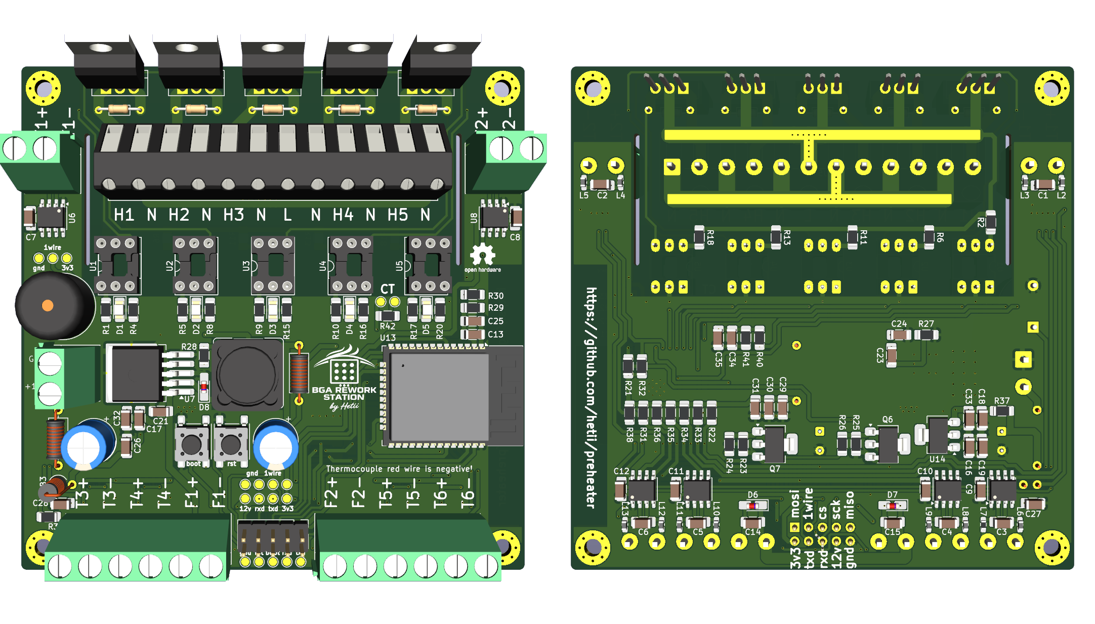
BGA Rework Station is a fully open-source project designed for controlling professional and DIY BGA/PCB preheating systems.
The controller supports multiple heating zones, thermocouple monitoring, fan control, and a modern web-based interface for managing the entire process directly from a browser.
The project is suitable for:
Built-in web application accessible from any browser.
Features include:
| Feature | Specification |
|---|---|
| Heater Outputs | Up to 5 |
| Thermocouple Inputs | 6 |
| Fan Control | 2 x PWM Supported |
| Interface | Web Browser |
| Profile Storage | Supported |
| Open Source | Yes |
├── docs
│   ├── datasheets
│   ├── img
│   └── pdf
├── hardware
│   ├── gerbers
│   ├── gerbers.sh
│   └── kicad
├── README.md
└── software
    ├── backend
    ├── frontend
    ├── Makefile
    ├── mock
└── secrets.yamlbackend/ — reserved for the real ESP32 (Arduino) firmware, stage 2frontend/ — Preact + TypeScript web UI (WebSocket telemetry + REST config)mock/ — Python mock of the ESP32 backend (aiohttp; full thermal simulation)make deps # install npm + python dependencies
make dev # run mock backend (:8000) + vite dev server (:5173)
make test # pytest for all REST/WS endpoints and the simulation
make lint # ruff + eslint + tsc
make frontend # production bundle (later embedded in ESP32 flash)Useful during development: MOCK_TIME_SCALE=10 make mock runs the thermal
simulation 10x faster than wall clock.
/ws: telemetry pushed every 500 ms, events
(step_done, profile_done, operator_needed, alarm),
commands (start, pause, resume, stop, confirm, set_fans).GET/POST /api/profiles, GET/PUT/DELETE /api/profiles/{id},
GET/PUT /api/settings, GET /api/status.The real ESP32 firmware (stage 2) must keep this contract unchanged.
| Qty | Value | Footprint | References |
|---|---|---|---|
| 18 | . | TestPoint:TestPoint_Pad_D1.5mm | TP1, TP2, TP3, TP4, TP5, TP6, TP7, TP10, TP11, TP12, TP13, TP14, TP15, TP16, TP17, TP18 +2 |
| 13 | 100nF | Capacitor_SMD:C_1206_3216Metric_Pad1.33x1.80mm_HandSolder | C7, C8, C9, C10, C11, C12, C13, C16, C17, C21, C24, C28, C35 |
| 11 | BLM18PG471SN1D | Inductor_SMD:L_0603_1608Metric_Pad1.05x0.95mm_HandSolder | L2, L3, L4, L5, L6, L8, L9, L10, L11, L12, L13 |
| 10 | 1k | Resistor_SMD:R_1206_3216Metric_Pad1.30x1.75mm_HandSolder | R21, R22, R27, R29, R31, R32, R33, R34, R35, R36 |
| 10 | 330 | Resistor_SMD:R_1206_3216Metric_Pad1.30x1.75mm_HandSolder | R1, R4, R5, R8, R9, R10, R15, R16, R17, R20 |
| 9 | 10nF | Capacitor_SMD:C_1206_3216Metric_Pad1.33x1.80mm_HandSolder | C1, C2, C3, C4, C5, C6, C14, C15, C23 |
| 9 | 10uF | Capacitor_SMD:C_1206_3216Metric_Pad1.33x1.80mm_HandSolder | C18, C19, C25, C27, C29, C30, C31, C33, C34 |
| 6 | MAX31855KASA | Package_SO:SOIC-8_3.9x4.9mm_P1.27mm | U6, U8, U9, U10, U11, U12 |
| 5 | 330 | Resistor_THT:R_Axial_DIN0204_L3.6mm_D1.6mm_P7.62mm_Horizontal | R3, R7, R12, R14, R19 |
| 5 | 360 | Resistor_SMD:R_1206_3216Metric_Pad1.30x1.75mm_HandSolder | R2, R6, R11, R13, R18 |
| 5 | BT139-800B | Package_TO_SOT_THT:TO-220-3_Vertical | Q1, Q2, Q3, Q4, Q5 |
| 5 | LED | LED_SMD:LED_1206_3216Metric_Pad1.42x1.75mm_HandSolder | D1, D2, D3, D4, D5 |
| 5 | MOC3041M | Package_DIP:DIP-6_W7.62mm_Socket_LongPads | U1, U2, U3, U4, U5 |
| 4 | 10k | Resistor_SMD:R_1206_3216Metric_Pad1.30x1.75mm_HandSolder | R23, R25, R40, R41 |
| 2 | 100 | Resistor_SMD:R_1206_3216Metric_Pad1.30x1.75mm_HandSolder | R24, R26 |
| 2 | 1N4148 | Diode_SMD:D_MicroMELF_Handsoldering | D6, D7 |
| 2 | 1nF | Capacitor_SMD:C_1206_3216Metric_Pad1.33x1.80mm_HandSolder | C26, C32 |
| 2 | FL024Z | Package_TO_SOT_SMD:SOT-223-3_TabPin2 | Q6, Q7 |
| 2 | FerriteBead | Inductor_THT:L_Axial_L7.0mm_D3.3mm_P10.16mm_Horizontal_Fastron_MICC | FB1, FB2 |
| 2 | RXD_SELECT | Resistor_SMD:R_0201_0603Metric | NT1, NT2 |
| 1 | *66 | Resistor_SMD:R_1206_3216Metric_Pad1.30x1.75mm_HandSolder | R42 |
| 1 | 10 | Resistor_SMD:R_1206_3216Metric_Pad1.30x1.75mm_HandSolder | R39 |
| 1 | 1N5825 | Diode_SMD:D_MicroMELF_Handsoldering | D8 |
| 1 | 1k68 | Resistor_SMD:R_1206_3216Metric_Pad1.30x1.75mm_HandSolder | R28 |
| 1 | 220 | Resistor_SMD:R_1206_3216Metric_Pad1.30x1.75mm_HandSolder | R37 |
| 1 | 220uF | Capacitor_THT:CP_Radial_D8.0mm_P3.50mm | C22 |
| 1 | 470uF | Capacitor_THT:CP_Radial_D8.0mm_P3.50mm | C20 |
| 1 | 47uH | Inductor_SMD:L_Bourns_SRR1260 | L1 |
| 1 | 4k7 | Resistor_SMD:R_1206_3216Metric_Pad1.30x1.75mm_HandSolder | R38 |
| 1 | 560 | Resistor_SMD:R_1206_3216Metric_Pad1.30x1.75mm_HandSolder | R30 |
| 1 | AMS1117-3.3 | Package_TO_SOT_SMD:SOT-223-3_TabPin2 | U14 |
| 1 | BLM18PG471SN1D | Resistor_SMD:R_0603_1608Metric_Pad0.98x0.95mm_HandSolder | L7 |
| 1 | BOOT | Button_Switch_SMD:SW_SPST_PTS645Sx43SMTR92 | SW1 |
| 1 | Buzzer | Buzzer_Beeper:Buzzer_12x9.5RM7.6 | BZ1 |
| 1 | Display | Connector_PinHeader_2.54mm:PinHeader_2x05_P2.54mm_Vertical | J6 |
| 1 | ESP32-WROOM-32E | RF_Module:ESP32-WROOM-32D | U13 |
| 1 | FerriteBead | Inductor_THT:L_Axial_L7.0mm_D3.3mm_P2.54mm_Vertical_Fastron_MICC | FB3 |
| 1 | H1 | MountingHole:MountingHole_3.2mm_M3_Pad_Via | H1 |
| 1 | H2 | MountingHole:MountingHole_3.2mm_M3_Pad_Via | H2 |
| 1 | H3 | MountingHole:MountingHole_3.2mm_M3_Pad_Via | H3 |
| 1 | H4 | MountingHole:MountingHole_3.2mm_M3_Pad_Via | H4 |
| 1 | Heaters | TerminalBlock_Altech:Altech_AK300_1x12_P5.00mm_45-Degree | J5 |
| 1 | LM2596S-ADJ | Package_TO_SOT_SMD:TO-263-5_TabPin3 | U7 |
| 1 | LOGO | LOGO | ... |
| 1 | RESET | Button_Switch_SMD:SW_SPST_PTS645Sx43SMTR92 | SW2 |
| 1 | TC1 | TerminalBlock_Altech:Altech_AK100_1x02_P5.00mm | J1 |
| 1 | TC2 | TerminalBlock_Altech:Altech_AK100_1x02_P5.00mm | J2 |
| 1 | TC3-4-FAN1 | TerminalBlock_Altech:Altech_AK100_1x06_P5.00mm | J3 |
| 1 | TC5-6-FAN2 | TerminalBlock_Altech:Altech_AK100_1x06_P5.00mm | J4 |
| 1 | VCC | TerminalBlock_Altech:Altech_AK100_1x02_P5.00mm | J7 |
The 157 most common of 158 parts.
It measures 92 × 92 mm and has 2 copper layers, 1.6 mm thick.
158 parts, built around the ESP32-WROOM-32E, MAX31855KASA+T, LM2596S-ADJ and MOC3041M. The full list of its parts is on this page, with links to each part's symbol and footprint where PCBKit's library has them.
From the hetii/preheater repository on GitHub, at the commit this page was made from: the board is hardware/kicad/preheater.kicad_pcb and its schematic hardware/kicad/preheater.kicad_sch. PCBKit opens the board in the browser, with nothing to install.
Its repository states no licence, so its author keeps all rights: ask hetii before reusing the design.


AlterMundi-MonitoreoyControl/Proyecto-Incubadora
Is an innovative project aimed at enhancing the efficiency and productivity of poultry incubators in family farming.

JuanCamilo0509/autoLights
This project has two main directories: - Software: Two main sub-directories, the light-Module where the code for the esp is maintain, and the "mosquitto-Server" with the ".conf" file for the server.


ghent360/PrntrBoard
3D Printer controller board using STM32 NUCLEO-F446 kit TMC2130/2660/2209 drivers

