

2 layers100 × 100 mm

 hdkghc/calculator
A computer algebra system project written in C++, built for the i.MX RT1011 crossover MCU.
Calculator is an open-source printed circuit board by hdkghc, from the hdkghc/calculator repository on GitHub, published under the GPL-3.0 licence. It is a 2-layer board of 81.3 × 131.4 mm with 65 parts on 68 nets, routed with 529 tracks and 74 vias.
It is built around the BC547 and S8550. Its parts include 37 switches, 14 resistors, 3 capacitors, 3 ICs and 2 transistors. It belongs with the RP2040, AVR (ATmega, ATtiny) and NXP (LPC, Kinetis, i.MX RT) boards of this library.
A scientific/graphical calculator firmware for Raspberry Pi Pico, with CAS (Computer Algebra System) and graphical display support.
PCB Preview ---->
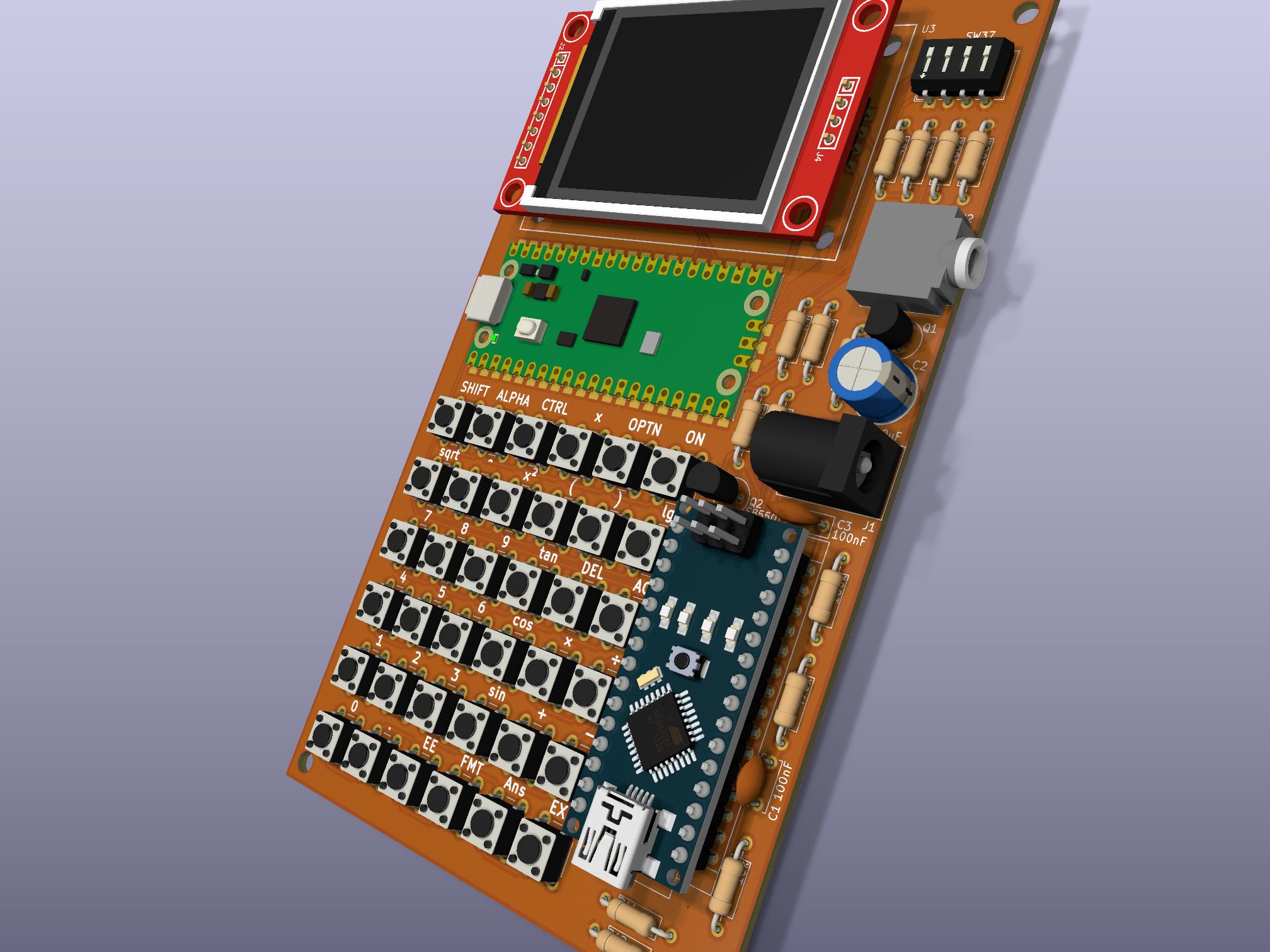
Status: Under active development. Core CAS and display subsystem are partially implemented; basic arithmetic, expression parsing, and simplification are functional. Integration and matrix operations are in progress.
hardware/kicad directory)Refer to wiring.txt (deprecated) and hardware/kicad/ for schematics and PCB design. Gerber files are available in hardware/gerber*.zip.
calculator/
├── CMakeLists.txt          # Build configuration
├── build.sh                # Convenience build script
├── inc/                    # Header files
│   ├── cas/                # CAS core (parser, simplifier, integrator, etc.)
│   └── dispinterface/      # Display abstraction
├── src/                    # Source files
│   ├── main.cpp            # Entry point
│   └── cas/                # CAS implementation
├── fonts/                  # Generated font data (ClassWiz style)
├── font2h/                 # Font conversion tools (font2h, preview)
├── hardware/               # PCB design (KiCad, Fritzing(deprecated), Gerber)
├── test/                   # Unit tests (CAS functions)
├── resources/              # Images (logo, PCB preview)
└── LICENSE # GPLv3git clone https://github.com/hdkghc/calculator.git
cd calculator./build.sh (automates CMake configuration and build).mkdir build && cd build
cmake ..
make.uf2 file to your Pico's mass storage device, or use picotool.arm-none-eabi-g++)This project is licensed under the GNU General Public License v3.0.
See LICENSE for details.
This is an amateur, non-commercial open‑source project. All hardware and software are provided “as is”, without any warranty. The author assumes no liability for any damage or injury resulting from the use, assembly, or modification of this project.
Contributions are welcome! Please read CONTRIBUTING.md for guidelines.
| Qty | Value | Footprint | References |
|---|---|---|---|
| 36 | SW_Push | Button_Switch_THT:SW_PUSH_6mm | SW1, SW2, SW10, SW11, SW12, SW13, SW14, SW15, SW16, SW17, SW18, SW19, SW20, SW21, SW22, SW23 +20 |
| 5 | 4k7 | Resistor_THT:R_Axial_DIN0207_L6.3mm_D2.5mm_P10.16mm_Horizontal | R3, R4, R5, R6, R14 |
| 4 | , , , | ||
| 4 | 100k | Resistor_THT:R_Axial_DIN0207_L6.3mm_D2.5mm_P10.16mm_Horizontal | R7, R8, R12, R13 |
| 2 | 330R | Resistor_THT:R_Axial_DIN0207_L6.3mm_D2.5mm_P10.16mm_Horizontal | R1, R2 |
| 1 | 100nF | Capacitor_THT:C_Disc_D7.0mm_W2.5mm_P5.00mm | C3 |
| 1 | 100nF | Capacitor_THT:C_Disc_D6.0mm_W2.5mm_P5.00mm | C1 |
| 1 | 10k | Resistor_THT:R_Axial_DIN0207_L6.3mm_D2.5mm_P10.16mm_Horizontal | R11 |
| 1 | 1M | Resistor_THT:R_Axial_DIN0207_L6.3mm_D2.5mm_P10.16mm_Horizontal | R9 |
| 1 | 25V 100uF | Capacitor_THT:CP_Radial_D8.0mm_P3.50mm | C2 |
| 1 | 470k | Resistor_THT:R_Axial_DIN0207_L6.3mm_D2.5mm_P10.16mm_Horizontal | R10 |
| 1 | Arduino_Nano_v2.x | Module:Arduino_Nano | U2 |
| 1 | AudioJack3_SwitchTR | Connector_Audio:Jack_3.5mm_CUI_SJ1-3525N_Horizontal | J2 |
| 1 | BC547 | Package_TO_SOT_THT:TO-92_Inline_Wide | Q1 |
| 1 | Jack-DC | Connector_BarrelJack:BarrelJack_Kycon_KLDX-0202-xC_Horizontal | J1 |
| 1 | Pico | MCU_RaspberryPi_and_Boards:RPi_Pico_SMD_TH | U1 |
| 1 | S8550 | Package_TO_SOT_THT:TO-92_Inline_Wide | Q2 |
| 1 | SW_DIP_x04 | Button_Switch_THT:SW_DIP_SPSTx04_Slide_6.7x11.72mm_W7.62mm_P2.54mm_LowProfile | SW37 |
| 1 | TFT | MSP1803_TFT_12pin_Library:MSP1803_TFT_12pin | U3 |
It measures 81.3 × 131.4 mm and has 2 copper layers, 1.6 mm thick.
65 parts, built around the BC547 and S8550. The full list of its parts is on this page, with links to each part's symbol and footprint where PCBKit's library has them.
From the hdkghc/calculator repository on GitHub, at the commit this page was made from: the board is hardware/kicad/calculator.kicad_pcb and its schematic hardware/kicad/calculator.kicad_sch. PCBKit opens the board in the browser, with nothing to install.
Its repository publishes it under the GPL-3.0 licence: you may reuse it on that licence's terms (keep the author's notice, and for a copyleft licence share your changes alike).


twam/IEC-62056-21-Optical-Probe
Optical-Probe for reading out power meters supporting IEC 62056-21 via USB

szbeni/forcegauge
Traning for climbing. Load cell with HX711 and real time plotting,

zargony/touch-n-drink
Hardware and firmware for cashless payment device for cold drinks at the aeroclub at EDLH

roybaer/sound_source
Design documents for Disney Sound Source (DSS) compatible hardware

cjheath/jlcbasic
JLC Basic parts library for Kicad fetched and converted from EasyEDA

IoTReady/esp32-wifi-ble-weighing-scale
This is a weighing scale designed to share data over Wi-Fi using esp32 WROOM32 module. For the weighing scale we are using a load cell and measuring the output using a HX711 24-bit ADC designed for weigh scales and…