4 layers200 × 100 mm
Heteromycin
hasenbanck/heteromycin
A 3D printer board using a powerfull STM32 MCU, TMC5160/TMC2160 driver and a Raspberry Pi or compatible SBC
373 parts40

 hasenbanck/remram40
32bit STM32F7 based 3D printing controller using TMC2130 stepper driver
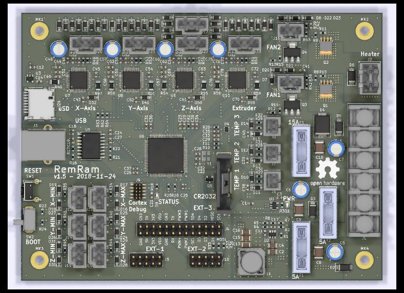
Remram is an open-source printed circuit board by hasenbanck, from the hasenbanck/remram repository on GitHub. It is a 4-layer board of 140 × 104 mm with 264 parts on 269 nets, routed with 1,827 tracks and 551 vias.
It is built around the STM32F765VIT6, SN74LVC2G17DCKR and TMC2130-TA-T, with the ADUM4160BRW, TPS54308DDC and S310FA among its other parts. Its parts include 78 capacitors, 67 diodes, 65 resistors, 24 connectors and 10 ICs. It belongs with the STM32 boards of this library.


Software used KiCad 5.0
You can substitute the TPS5408 with a TPS5402. In this case you also need to replace R4 with a Zero Ohm resistor.
These are the board specific Configuration.h changes:
#define SERIAL_PORT 1 // 1 = UART connection on EXT3
                      // -1 = Serial over USB (see: Virtual COM Port Support (Serial over USB))
                      // You can also configure SERIAL_PORT_2

#define BAUDRATE 115200 // 115200 for UART on EXT3
                        // 1000000 for Serial over USB

#define MOTHERBOARD BOARD_REMRAM_V1

#define X_DRIVER_TYPE  TMC2130
#define Y_DRIVER_TYPE  TMC2130
#define Z_DRIVER_TYPE  TMC2130
#define E0_DRIVER_TYPE TMC2130

#define ENDSTOP_INTERRUPTS_FEATURE

#define SDSUPPORT
These are the board specific Configuration_adv.h changes:
#define MINIMUM_STEPPER_DIR_DELAY 20
#define MINIMUM_STEPPER_PULSE 0
#define MAXIMUM_STEPPER_RATE 400000

#if HAS_TRINAMIC

  // You can change ever value EXCEPT R_SENSE based on your setup.
  // Example values of my HEVO setup

  #define R_SENSE           0.12  // DO NOT CHANGE! Need to be 0.12 for RemRam V1
  #define HOLD_MULTIPLIER    0.3  // Scales down the holding current from run current
  #define INTERPOLATE       true  // Interpolate X/Y/Z_MICROSTEPS to 256

  #define X_CURRENT          750  // rms current in mA. Multiply by 1.41 for peak current.
  #define X_MICROSTEPS       256  // 0..256

  #define Y_CURRENT          750
  #define Y_MICROSTEPS       256

  #define Z_CURRENT          750
  #define Z_MICROSTEPS       256

  #define E0_CURRENT         400
#define E0_MICROSTEPS 256src/pins/pins_REMRAM_V1.h
// Use only one or the other (you could damage the hardware otherwise!)
#define SDSS               57   // Onboard SD card reader
//#define SDSS              9   // LCD SD card reader
Of course you need to aditionally change the configuration files based on your particular printer setup.
Virtual COM Port (also known as VCOM or CDC) support will land in the "official" STM32 arduino core with version 1.5.0. If you want to use VCOM feature earlier, you can use the the master branch of the offical core.
Have a look at the "Update the STM32 Core using the git repository" on how to update the STM32 arduino core with a custom git branch. You also have to select "CDC Full Speed" as USB interface inside Arduino to enable the CDC interface.
Most RepRapDiscount based LCD modules come with an integrated SD card reader. You can use this reader, but because this system is 3.3V based, the signal to noise ration is higher. Meaning you will need a much better connection between the LCD module and the board. Crappy ribbon cables won't do it in most cases. Dropping the SPI speed AND using shielded ribbon cables is most likely needed to get a good signal integrity.
You can't use the onboard SD card reader and the LCD card reader at the same time. DO NOT insert a SD card in both slots at the same time, because this could lead to a hardware failure.
Supported:
You can use the Cortex Debug Header to program the STM32 firmware and do step-by-step debugging.
This board only support SWD. SWO is not routed to the header, since we had to use the pin for a PWM output.
I personally use the SEGGER J-Link Edu Mini. But any 2€ Ebay flasher should work ("ST Link V2"). Please make sure that you have a adapter for the debug header!
The debug header is a 2x05 pin (1.27/0.05”).
https://www.st.com/en/development-tools/stsw-stm32080.html
Please pay attention that you don't just flash the HEX/BIN file, but the special DFU image file (*.dfu) you need to create with the "DFU file manager" tool. DfuSe will let you happily flash a HEX/BIN file, but the board won't boot without a propper DFU file.
Please read the "UM0412" user manual you can find at the above link.
https://www.st.com/en/development-tools/flasher-stm32.html
CERN OHL version 1.2
The files under PCB/packages3d are excluded from this license and are provided under fair use terms for this open-source project.
| Qty | Value | Footprint | References |
|---|---|---|---|
| 39 | 100nF | Capacitor_SMD:C_0603_1608Metric | C11, C18, C19, C21, C22, C23, C24, C25, C27, C28, C31, C33, C34, C35, C38, C39 +23 |
| 36 | S310FA | Diode_SMD:D_SOD-123 | D32, D33, D34, D35, D36, D37, D38, D39, D40, D41, D42, D43, D44, D45, D46, D47 +20 |
| 24 | BAT54GWJ | Diode_SMD:D_SOD-123 | D10, D11, D12, D13, D14, D15, D16, D17, D18, D19, D20, D21, D22, D23, D24, D25 +8 |
| 13 | 47k | Resistor_SMD:R_0603_1608Metric | R23, R24, R48, R49, R52, R53, R56, R57, R60, R61, R62, R63, R64 |
| 11 | 100 | Resistor_SMD:R_0603_1608Metric | R8, R9, R12, R13, R16, R17, R21, R22, R33, R36, R37 |
| 11 | 4.7k | Resistor_SMD:R_0603_1608Metric | R27, R28, R29, R30, R31, R32, R38, R39, R42, R43, R65 |
| 10 | 1k | Resistor_SMD:R_0603_1608Metric | R3, R18, R19, R20, R34, R35, R40, R41, R44, R45 |
| 8 | 0.12 | Resistor_SMD:R_1206_3216Metric | R46, R47, R50, R51, R54, R55, R58, R59 |
| 8 | 10uF | Capacitor_SMD:C_0603_1608Metric | C1, C3, C12, C14, C50, C59, C68, C77 |
| 8 | 70543-0002 | custom-footprints:70543-0002 | J11, J12, J13, J14, J15, J16, J18, J19 |
| 7 | 100uF | Capacitor_THT:CP_Radial_D6.3mm_P2.50mm | C5, C6, C7, C48, C57, C66, C75 |
| 5 | 100k | Resistor_SMD:R_0603_1608Metric | R6, R10, R11, R14, R15 |
| 5 | 70543-0003 | custom-footprints:70543-0003 | J17, J20, J21, J22, J23 |
| 4 | 22nF | Capacitor_SMD:C_0603_1608Metric | C46, C55, C64, C73 |
| 4 | 470nF | Capacitor_SMD:C_0603_1608Metric | C47, C56, C65, C74 |
| 4 | Mounting_Hole_PAD | MountingHole:MountingHole_3.5mm_Pad | MK1, MK2, MK3, MK4 |
| 4 | TMC2130-TA | custom-footprints:TQFP-48-1EP_7x7mm_P0.5mm_EP4.8x4.8mm-Heatsink | U7, U8, U9, U10 |
| 3 | 100nF | Capacitor_SMD:C_1812_4532Metric | C8, C9, C10 |
| 3 | 22uF | Capacitor_SMD:C_1206_3216Metric | C13, C15, C16 |
| 3 | 3557-2 | custom-footprints:KEYSTONE-FUSE-3557-2 | F1, F2, F3 |
| 3 | 70543-0001 | custom-footprints:70543-0001 | J6, J7, J8 |
| 2 | 10k | Resistor_SMD:R_0603_1608Metric | R25, R26 |
| 2 | 1uF | Capacitor_SMD:C_0603_1608Metric | C29, C30 |
| 2 | 2.2uF | Capacitor_SMD:C_0603_1608Metric | C36, C37 |
| 2 | 8pF | Capacitor_SMD:C_0603_1608Metric | C26, C32 |
| 2 | AP7365-33WG-7 | Package_TO_SOT_SMD:SOT-23-5 | U1, U3 |
| 2 | BUK9840-55 | Package_TO_SOT_SMD:SOT-223-3_TabPin2 | Q3, Q4 |
| 2 | Conn_02x05 | Connector_PinHeader_2.54mm:PinHeader_2x05_P2.54mm_Vertical | J5, J10 |
| 2 | MPZ1608S221A | Resistor_SMD:R_0603_1608Metric | FB1, FB2 |
| 2 | PSMN1R2-30YLC,115 | custom-footprints:SOT-669_LFPAK_ThermalVias-1 | Q1, Q2 |
| 2 | SK310A-LTP | Diode_SMD:D_SMA | D5, D6 |
| 2 | SMAJ28A | Diode_SMD:D_SMA | D2, D3 |
| 1 | 039531-1002 | custom-footprints:39531-1002 | J2 |
| 1 | 100nF | Capacitor_SMD:C_1206_3216Metric | C4 |
| 1 | 105k | Resistor_SMD:R_0603_1608Metric | R2 |
| 1 | 10uF | Capacitor_SMD:C_1206_3216Metric | C2 |
| 1 | 13.3k | Resistor_SMD:R_0603_1608Metric | R7 |
| 1 | 18uH | custom-footprints:L_Wuerth_WE-PDF | L1 |
| 1 | 20021121-00010C4LF | custom-footprints:PinHeader_2x05_P1.27mm_Vertical_SMD | J9 |
| 1 | 2k | Resistor_SMD:R_0603_1608Metric | R4 |
| 1 | 4.7uF | Capacitor_SMD:C_0603_1608Metric | C20 |
| 1 | 49.9 | Resistor_SMD:R_0603_1608Metric | R5 |
| 1 | 4DB-P108-06 | custom-footprints:4DB-P108-06 | J1 |
| 1 | 511k | Resistor_SMD:R_0603_1608Metric | R1 |
| 1 | 67068-8000 | custom-footprints:67068-8000 | J3 |
| 1 | 75pF | Capacitor_SMD:C_0603_1608Metric | C17 |
| 1 | ADUM4160 | Package_SO:SOIC-16W_7.5x10.3mm_P1.27mm | U5 |
| 1 | Conn_02x13_Odd_Even | custom-footprints:PinHeader_2x13_P2.54mm_Vertical | J4 |
| 1 | Hirose DM3D | custom-footprints:microSD_HC_Hirose_DM3D-SF | J24 |
| 1 | IRLML6401 | Package_TO_SOT_SMD:SOT-23 | Q5 |
| 1 | LTST-C194KGKT | LED_SMD:LED_0603_1608Metric | D1 |
| 1 | LTST-C194KSKT | LED_SMD:LED_0603_1608Metric | D9 |
| 1 | Logo_Open_Hardware_Large | Symbol:OSHW-Logo2_14.6x12mm_SilkScreen | LOGO1 |
| 1 | OS102011MA1QN1 | custom-footprints:SW_CuK_OS102011MA1QN1_SPDT_Angled | SW2 |
| 1 | PTS645VL39-2 | Button_Switch_THT:SW_Tactile_SPST_Angled_PTS645Vx39-2LFS | SW1 |
| 1 | S3A-13-F | Diode_SMD:D_SMC | D4 |
| 1 | S8401-46 | custom-footprints:S8401-46 | BT1 |
| 1 | SN74LVC2G17DCKR | custom-footprints:SOT-363_SC-70-6 | U4 |
| 1 | STM32F765VIT6 | custom-footprints:TQFP-100_14x14mm_P0.5mm | U6 |
| 1 | TPS54308 | Package_TO_SOT_SMD:SOT-23-6 | U2 |
| 1 | TSX-3225 24.0000MF15X-AC3 | Crystal:Crystal_SMD_SeikoEpson_TSX3225-4Pin_3.2x2.5mm | Y1 |
hasenbanck/heteromycin
A 3D printer board using a powerfull STM32 MCU, TMC5160/TMC2160 driver and a Raspberry Pi or compatible SBC

Crate3D/closed-loop-stepper-tmc2130-as5048a
Closed loop stepper using tmc2130 and as5048a

Prachannagven/stm32f765-facial-detection
A project built around the STM32F765VIT6 chip to perform basic facial detection and to act as a flight controller for a micro drone.


wiretap-retro/Not-A-Varta-CR2032
Similar to the "Not-A-Varta", but with a vertical CR2032 holder, and elongated mounting holes.


rodrigue-laboratory/pipette-tool-pcb
bash kicad-cli pcb export gerbers pipettetool.kicadpcb --output fab/gerbers kicad-cli pcb export drill pipettetool.kicadpcb --output fab/gerbers --format excellon
It measures 140 × 104 mm and has 4 copper layers, 1.6 mm thick.
264 parts, built around the STM32F765VIT6, SN74LVC2G17DCKR, TMC2130-TA-T and ADUM4160BRW. The full list of its parts is on this page, with links to each part's symbol and footprint where PCBKit's library has them.
From the hasenbanck/remram repository on GitHub, at the commit this page was made from: the board is PCB/remram.kicad_pcb. PCBKit opens the board in the browser, with nothing to install.
Its repository states no licence, so its author keeps all rights: ask hasenbanck before reusing the design.