2 layers49.5 × 49.5 mm
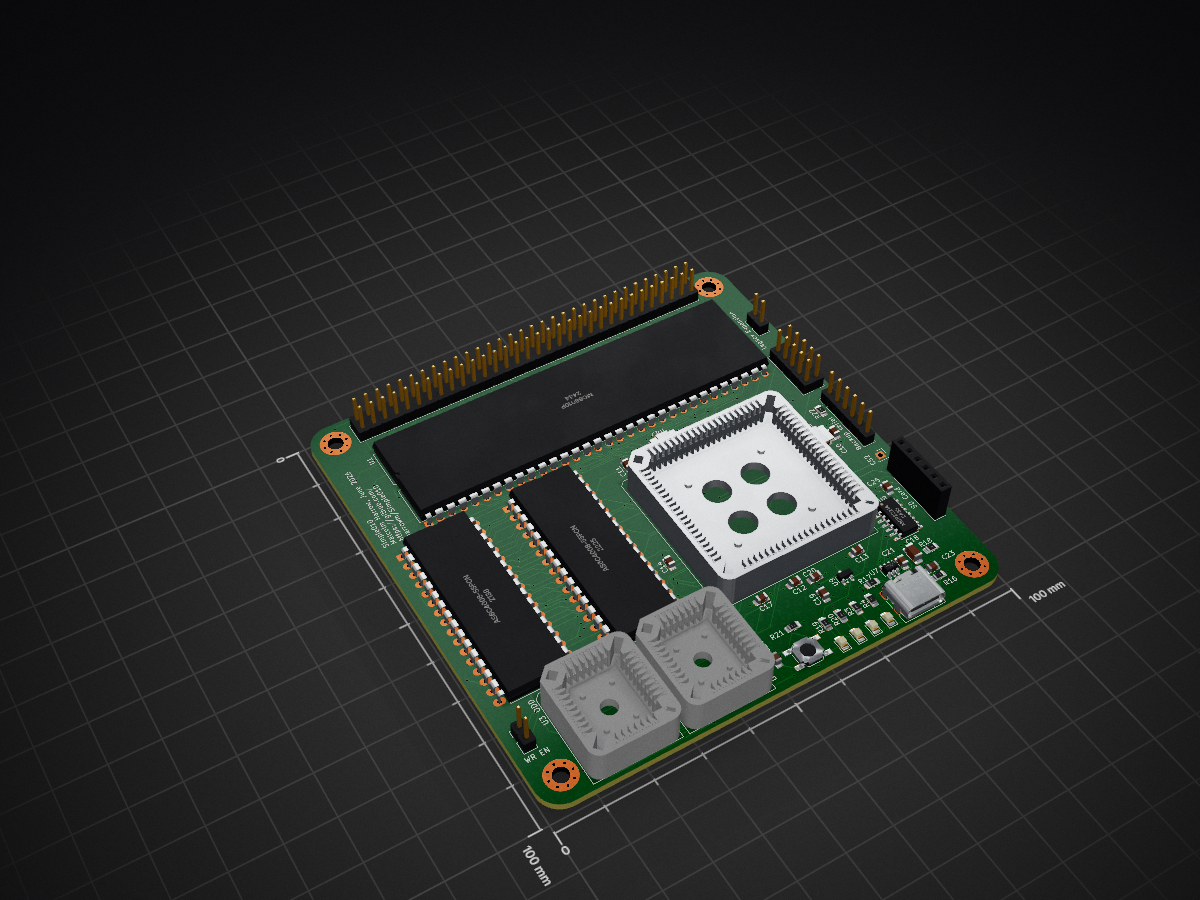
 harrowm/Simple0101
68010 SBC using a ATF1608 CPLD based on teh rosco_m68k SBC
Simple010-16 is an open-source printed circuit board by harrowm, from the harrowm/Simple010 repository on GitHub, published under the MIT licence. It is a 4-layer board of 100 × 100 mm with 75 parts on 124 nets, routed with 2,839 tracks and 241 vias.
It is built around the MCP2221A-I/P, AS6C4008-55PCN and USBLC6-2SC6. Its parts include 25 capacitors, 22 resistors, 9 ICs, 6 connectors and 4 diodes. It belongs with the computers and single-board computers and fPGA and programmable logic boards and the FPGA and CPLD boards of this library.


A 68010 single-board computer based on the rosco_m68k r2 design. Simple010 replaces the six discrete glue-logic ICs from that design with a single ATF1508AS PLCC84 CPLD, reducing board complexity while adding hardware SPI acceleration for SD card access.
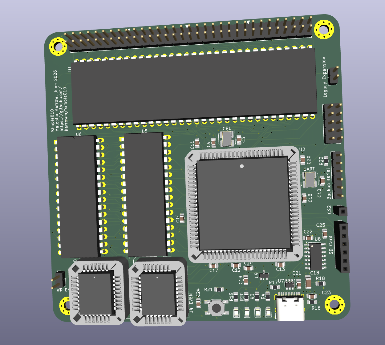
| Item | Detail |
|---|---|
| CPU | Motorola MC68010P at 10 MHz |
| RAM | 1 MB — two AS6C4008-55PCN SRAMs (even/odd byte lanes) |
| ROM | Two SST39SF040 4 Mb flash (even/odd byte lanes) |
| CPLD | ATF1508AS PLCC84 — replaces IC2/IC3/IC4/IC5/IC6/IC7 from rosco_m68k r2 |
| USB/serial | MCP2221A — USB-CDC serial to UART A. The original rosco_m68k board has two UARTs A and B. However, the code for two UARTs won't fit into the CPLD, so a cheaper one-channel USB-to-serial chip is used. |
| PCB | 4-layer, 100 × 100 mm, JLCPCB stackup (F.Cu / GND / PWR / B.Cu) |
| Range | Device |
|---|---|
$000000–$0FFFFF | 1 MB SRAM |
$100000–$DFFFFF | Expansion bus (DTACK from LGEXP) |
$E00000–$EFFFFF | Flash ROM |
$F00000–$FFFFFF | I/O — CPLD UART at $F00000, register select via A1–A4 |
The CPLD (code/cpld/cpld.v) implements:
Resource utilisation: 122/128 macro cells (95%).
design/
  Simple010/            KiCad 10 schematic and PCB (1 MB SRAM)
    Simple010.kicad_sch   top-level (references four sub-sheets)
    CPU.kicad_sch         MC68010P, oscillator, expansion connector
    Memory.kicad_sch      SRAM, ROM, write-enable jumper
    CPLD.kicad_sch        ATF1508AS, JTAG header, LEDs, pull-ups
    USB.kicad_sch         MCP2221A, SD card, reset supervisor, power LEDs
    production/           Gerbers, BOM, position file
  Simple010-16/         KiCad 10 schematic and PCB (16 MB SRAM variant)
  datasheets/           component datasheets and parts index (INDEX.md)

code/cpld/       ATF1508AS Verilog RTL and testbench
  cpld.v                RTL source with //PIN: preassignment comments
  tb_cpld.v             testbench (120 assertions)
  build.sh              synthesis → fit → pin check → simulation
  cpld.jed              program this into the device
  cpld.fit / cpld.pin   fitter log and pin placement

rosco/ rosco_m68k firmware (git clone), modified for Simple010Requires atf15xx_yosys cloned into ~/atf15xx_yosys, and iverilog/vvp on PATH.
cd code/cpld && ./build.shExpected output: 122/128 MCs used and 120/120 tests passed.
To run the testbench without re-synthesising:
cd code/cpld && iverilog -DSIMULATION -o tb_cpld tb_cpld.v cpld.v && vvp tb_cpldThe -DSIMULATION flag is required — without it 2 of 120 tests fail due to a cross-clock-domain handshake that behaves differently under deterministic simulation timing.
The firmware is the standard rosco_m68k r2 firmware cloned into rosco/, with minimal changes for Simple010 hardware.
The rosco directory is a clone of rosco-m68k/rosco_m68k. Simple010 changes are on the develop branch, pushed to a fork at harrowm/rosco_m68k. The upstream is origin; the fork is fork:
cd rosco/rosco_m68k
git add <files>
git commit -m "description"
git push fork developThe CPLD's UART emulates the XR68C681 (MC68681) at the register level. The existing rosco firmware DUART detection and initialisation code works without modification: the CPLD returns 0x0F from the IVR register at reset, exactly as the real XR68C681 does.
stage1/main1.cAt startup, after printing the standard CPU and memory information, the firmware reads the CPLD detection register and prints additional messages:
MC68010 CPU @ 10.0MHz with 1048576 bytes RAM
Simple010 CPLD v1 detected
  SPI RX accelerator present
Detection mechanism: reading byte address 0xF00005 (DUART_R_MISR in machine.h) returns a fixed capability byte from the CPLD:
| Bit | Mask | Meaning |
|---|---|---|
| 7 | 0x80 | CPLD present (always 1) |
| 6 | 0x40 | SPI RX accelerator available |
| 1–0 | 0x03 | Bitstream version (currently 1) |
The combined value is 0xC1. On the original XR68C681, this register is MISR (masked interrupt status), which reads ~0x00 at boot — so the detection is safe on original rosco hardware and the CPLD messages simply do not appear.
Address note: the CPLD's
uart_selis gated on~LDS(lower data strobe), so the access must target the odd byte address0xF00005. Reading even address0xF00004(upper data strobe / UDS) will not reach the CPLD.
stage1/blockdev/bbspi.cThe CPLD includes a hardware SPI byte-receive engine clocked at ~1.843 MHz (UART_CLK ÷ 2), reducing per-byte bus traffic from ~24 cycles to 2 cycles compared to bit-banging.
BBSPI_initialize() detects the accelerator by reading 0xF00005 and caches the result in a static bool cpld_spi_accel. BBSPI_recv_byte() and BBSPI_recv_buffer() then dispatch on this flag:
Accelerated receive sequence (per byte):
| Step | Action | Address |
|---|---|---|
| 1 | Write any value to SPIRX register — triggers one 8-bit receive | 0xF00009 (write) |
| 2 | Poll SRA bit 2 (spi_busy) until clear | 0xF00003 (read) |
| 3 | Read received byte from SPIRX register | 0xF00009 (read) |
Send operations (BBSPI_send_byte, BBSPI_send_buffer) are unchanged — they continue to bit-bang through the CPLD GPIO, which is correct since the SD card protocol is heavily read-biased and transmit calls are infrequent. On original rosco hardware, cpld_spi_accel is false and both receive functions fall back to the existing bit-bang asm routines in dua_spi_asm.asm.
See design/datasheets/INDEX.md for a full BOM with LCSC and Mouser part numbers.
Key sourcing notes:
Simple010 is based on the rosco_m68k project by Ross Bamford and contributors. The schematic topology, memory map, and firmware are derived from the rosco_m68k r2 mainboard design.
| Qty | Value | Footprint | References |
|---|---|---|---|
| 20 | 100nF | Capacitor_SMD:C_0805_2012Metric_Pad1.18x1.45mm_HandSolder | C1, C2, C3, C5, C10, C11, C12, C13, C14, C15, C16, C17, C20, C21, C22, C24 +4 |
| 11 | 4K7 | Resistor_SMD:R_0805_2012Metric_Pad1.20x1.40mm_HandSolder | R6, R7, R8, R9, R10, R11, R12, R13, R14, R15, R22 |
| 5 | 1K | Resistor_SMD:R_0805_2012Metric_Pad1.20x1.40mm_HandSolder | R3, R4, R19, R20, R21 |
| 4 | MountingHole_Pad | MountingHole:MountingHole_3.2mm_M3_Pad_Via | H1, H2, H3, H4 |
| 2 | 10K | Resistor_SMD:R_0805_2012Metric_Pad1.20x1.40mm_HandSolder | R1, R2 |
| 2 | 10uF | Capacitor_SMD:C_0805_2012Metric_Pad1.18x1.45mm_HandSolder | C4, C19 |
| 2 | 5.1k | Resistor_SMD:R_0805_2012Metric_Pad1.20x1.40mm_HandSolder | R17, R18 |
| 2 | AS6C4008-55PCN | Package_DIP:DIP-32_W15.24mm_LongPads | U5, U6 |
| 2 | GREEN | LED_SMD:LED_0805_2012Metric_Pad1.15x1.40mm_HandSolder | LED1, LED3 |
| 2 | RED | LED_SMD:LED_0805_2012Metric_Pad1.15x1.40mm_HandSolder | LED2, LED4 |
| 2 | SST39SF040 | Package_LCC:PLCC-32_THT-Socket | U3, U4 |
| 1 | 100pF | Capacitor_SMD:C_0805_2012Metric_Pad1.18x1.45mm_HandSolder | C23 |
| 1 | 1K2 | Resistor_SMD:R_0805_2012Metric_Pad1.20x1.40mm_HandSolder | R5 |
| 1 | 1M | Resistor_SMD:R_0805_2012Metric_Pad1.20x1.40mm_HandSolder | R16 |
| 1 | 470nF | Capacitor_SMD:C_0805_2012Metric_Pad1.18x1.45mm_HandSolder | C25 |
| 1 | 47uF | Capacitor_SMD:C_1206_3216Metric_Pad1.33x1.80mm_HandSolder | C18 |
| 1 | ATF1508ASx-xxJx84 | Package_LCC:PLCC-84_THT-Socket | U2 |
| 1 | Backup serial | Connector_PinHeader_2.54mm:PinHeader_1x06_P2.54mm_Vertical | J4 |
| 1 | CS2 | Connector_PinSocket_2.54mm:PinSocket_1x01_P2.54mm_Vertical | J1 |
| 1 | Conn_02x05_Odd_Even | Connector_PinHeader_2.54mm:PinHeader_2x05_P2.54mm_Vertical | J2 |
| 1 | Conn_02x32_Odd_Even | Connector_PinHeader_2.54mm:PinHeader_2x32_P2.54mm_Vertical | J7 |
| 1 | LM809M3-4.63/NOPB | Package_TO_SOT_SMD:SOT-23 | U9 |
| 1 | Legacy Expansion | Connector_PinHeader_2.54mm:PinHeader_1x02_P2.54mm_Vertical | JP2 |
| 1 | MC68010P | Package_DIP:DIP-64_W22.86mm | U1 |
| 1 | MCP2221A | Package_SO:SOIC-14_3.9x8.7mm_P1.27mm | U8 |
| 1 | ROM WR Enable | Connector_PinHeader_2.54mm:PinHeader_1x02_P2.54mm_Vertical | JP1 |
| 1 | Reset | Button_Switch_SMD:SW_SPST_SKQG_WithoutStem | SW1 |
| 1 | SD Card | Connector_PinSocket_2.54mm:PinSocket_1x06_P2.54mm_Vertical | J8 |
| 1 | SG-5032CAN 10MHz | Oscillator:Oscillator_SMD_SeikoEpson_SG8002LB-4Pin_5.0x3.2mm_HandSoldering | Y1 |
| 1 | SG-5032CAN 3.6864MHz | Oscillator:Oscillator_SMD_SeikoEpson_SG8002LB-4Pin_5.0x3.2mm_HandSoldering | Y2 |
| 1 | USBLC6-2SC6 | Package_TO_SOT_SMD:SOT-23-6 | U7 |
| 1 | USB_C_Receptacle_USB2.0_16P | Connector_USB:USB_C_Receptacle_HRO_TYPE-C-31-M-12 | J3 |
It measures 100 × 100 mm and has 4 copper layers, 1.6 mm thick.
75 parts, built around the MCP2221A-I/P, AS6C4008-55PCN and USBLC6-2SC6. The full list of its parts is on this page, with links to each part's symbol and footprint where PCBKit's library has them.
From the harrowm/Simple010 repository on GitHub, at the commit this page was made from: the board is design/Simple010-16/Simple010-16.kicad_pcb and its schematic design/Simple010-16/CPLD.kicad_sch. PCBKit opens the board in the browser, with nothing to install.
Its repository publishes it under the MIT licence: you may reuse it on that licence's terms (keep the author's notice, and for a copyleft licence share your changes alike).

bigbass1997/PICTAS
Low-cost replay device for playing back Tool Assisted Speedruns on real hardware

obskyr/f-ramune
A device for testing and programming FRAM chips! Finally you can be sure that FRAM you bought from China works.

bigbass1997/remote64
Provides a method for N64 homebrew developers to test their roms on remote hardware


gcoonrod/circuit-tap
Licensed under the Apache License, Version 2.0 (the "License"); you may not use this file except in compliance with the License. You may obtain a copy of the License at