2 layers
6502-schematic
lolakkalol/6502-computer-project
A 6502-based computer project! Explore the docs » View Demo Programs · Report Bug · Request Feature
57 parts

 gcoonrod/circuit-tap
Licensed under the Apache License, Version 2.0 (the "License"); you may not use this file except in compliance with the License. You may obtain a copy of the License at
Circuit tap is an open-source printed circuit board by gcoonrod, from the gcoonrod/circuit-tap repository on GitHub, published under the Apache-2.0 licence. It is a 4-layer board of 99.1 × 75.7 mm with 65 parts on 119 nets, routed with 654 tracks and 19 vias.
It is built around the ATMEGA4809-PF, MCP2221A-I/P and CD74HC165E, with the ACH-20.000MHZ-EK and UJ2-BH-1-TH among its other parts. Its parts include 18 capacitors, 11 connectors, 8 ICs, 8 diodes and 6 resistors. It belongs with the AVR (ATmega, ATtiny) boards of this library.


A low-speed digital logic analyzer designed around 74HC165 shift registers and the ATMega4809 MCU.
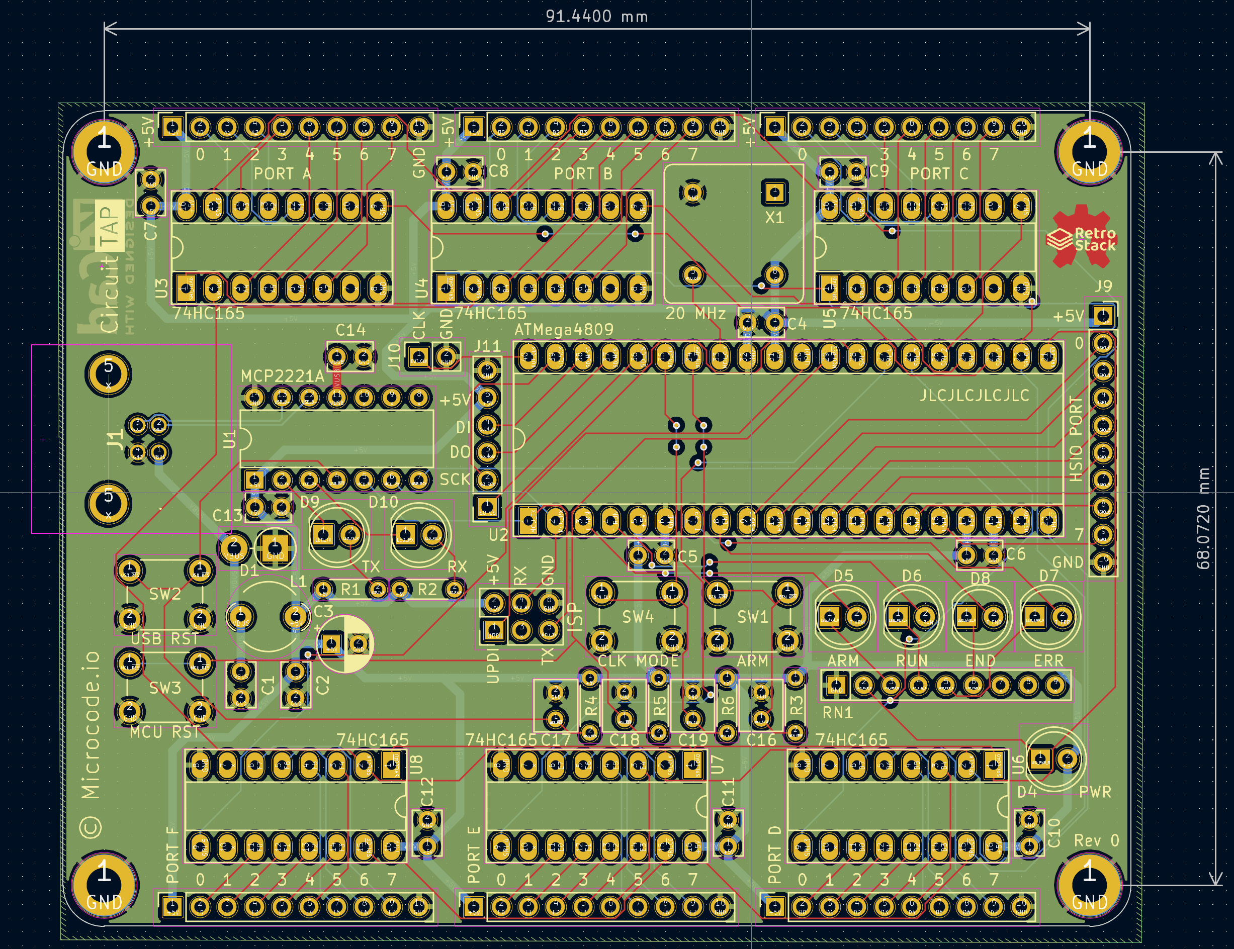
The Circuit Tap is designed to serve as a digital logic analyzer for primarily low speed circuits (<= 1Mhz). It is intended to aid in debugging the RetroStack, a 6502 based hobbyist computer. As I do not (at the time of designing this tool) own an oscilliscope or logic analyzer, I needed a way to monitor the address bus, data bus, and numerous control signals of the RetroStack while the clock was freely running. For very simple programs it was sufficient to use a manually stepped clock to debug, but the addition of IO peripherals and more complex programs have made it prohibitively time consuming to continue manual clock control.
The Circuit Tap has 6 low speed 8-bit input ports and one full speed 8-bit port. The low speed ports are implemented with 74HC165 parallel load shift registers which allows for the simultaneous capture of up to 48 signals on a single clock transition. However, those bits must be shifted out before (~10 mcu clock cycles) before another sample can be taken. This is the primary limiting factor for the sampling speed of the low speed inputs. The full speed port is directly mapped to Port D of the 4809 and can be read from or written to as fast as the mcu is capable.
| Qty | Value | Footprint | References |
|---|---|---|---|
| 12 | 100n | Capacitor_THT:C_Rect_L4.0mm_W2.5mm_P2.50mm | C2, C4, C5, C6, C7, C8, C9, C10, C11, C12, C13, C14 |
| 6 | 1k | Resistor_THT:R_Axial_DIN0204_L3.6mm_D1.6mm_P5.08mm_Horizontal | R1, R2, R3, R4, R5, R6 |
| 6 | CD74HC165E | Package_DIP:DIP-16_W7.62mm_Socket_LongPads | U3, U4, U5, U6, U7, U8 |
| 4 | 1u | Capacitor_THT:C_Rect_L4.6mm_W3.8mm_P2.50mm_MKS02_FKP02 | C16, C17, C18, C19 |
| 4 | M3 | MountingHole:MountingHole_3.2mm_M3_DIN965_Pad | H1, H2, H3, H4 |
| 1 | 10n | Capacitor_THT:C_Rect_L4.0mm_W2.5mm_P2.50mm | C1 |
| 1 | 1k | Resistor_THT:R_Array_SIP9 | RN1 |
| 1 | 4u7 | Capacitor_THT:CP_Radial_D5.0mm_P2.50mm | C3 |
| 1 | 600R | Ferrite_THT:LairdTech_28C0236-0JW-10 | L1 |
| 1 | ACH-20.000MHZ-EK | Oscillator:Oscillator_DIP-8 | X1 |
| 1 | ATMEGA4809-PF | Package_DIP:DIP-40_W15.24mm_Socket_LongPads | U2 |
| 1 | HDR_DUT_CLK | Connector_PinSocket_2.54mm:PinSocket_1x02_P2.54mm_Vertical | J10 |
| 1 | HDR_HSIO | Connector_PinSocket_2.54mm:PinSocket_1x10_P2.54mm_Vertical | J9 |
| 1 | HDR_PORTA | Connector_PinSocket_2.54mm:PinSocket_1x10_P2.54mm_Vertical | J3 |
| 1 | HDR_PORTB | Connector_PinSocket_2.54mm:PinSocket_1x10_P2.54mm_Vertical | J4 |
| 1 | HDR_PORTC | Connector_PinSocket_2.54mm:PinSocket_1x10_P2.54mm_Vertical | J5 |
| 1 | HDR_PORTD | Connector_PinSocket_2.54mm:PinSocket_1x10_P2.54mm_Vertical | J6 |
| 1 | HDR_PORTE | Connector_PinSocket_2.54mm:PinSocket_1x10_P2.54mm_Vertical | J7 |
| 1 | HDR_PORTF | Connector_PinSocket_2.54mm:PinSocket_1x10_P2.54mm_Vertical | J8 |
| 1 | HDR_SD | Connector_PinSocket_2.54mm:PinSocket_1x06_P2.54mm_Vertical | J11 |
| 1 | HDR_UPDI | Connector_PinHeader_2.54mm:PinHeader_2x03_P2.54mm_Vertical | J2 |
| 1 | LED_ARM | LED_THT:LED_D5.0mm | D5 |
| 1 | LED_END | LED_THT:LED_D5.0mm | D8 |
| 1 | LED_ERR | LED_THT:LED_D5.0mm | D7 |
| 1 | LED_PWR | LED_THT:LED_D5.0mm | D4 |
| 1 | LED_RUN | LED_THT:LED_D5.0mm | D6 |
| 1 | LED_RX | LED_THT:LED_D5.0mm | D10 |
| 1 | LED_TX | LED_THT:LED_D5.0mm | D9 |
| 1 | LOGO | RetroStack:RetroStackFullLogo13x10mm | G*** |
| 1 | MCP2221A-I/P | Package_DIP:DIP-14_W7.62mm | U1 |
| 1 | P6KE-AT | Diode_THT:D_DO-15_P3.81mm_Vertical_AnodeUp | D1 |
| 1 | SW_ARM | Button_Switch_THT:SW_PUSH_6mm | SW1 |
| 1 | SW_CLK | Button_Switch_THT:SW_PUSH_6mm | SW4 |
| 1 | SW_MCU_RST | Button_Switch_THT:SW_PUSH_6mm | SW3 |
| 1 | SW_USB_RST | Button_Switch_THT:SW_PUSH_6mm | SW2 |
| 1 | UJ2-BH-1-TH | RetroStack:UJ2BH1TH | J1 |
The 63 most common of 65 parts.
lolakkalol/6502-computer-project
A 6502-based computer project! Explore the docs » View Demo Programs · Report Bug · Request Feature


Board-Outline/USB-Power-Injector
The USB Power Injector allows a convenient way to power up USB 2.0 devices from a lab power supply, while still allowing data transfer from the device to the host.


CounterPillow/achterart
An 8-way USB-to-UART converter board based on the CH348 chip


It measures 99.1 × 75.7 mm and has 4 copper layers, 1.61 mm thick.
65 parts, built around the ATMEGA4809-PF, MCP2221A-I/P, CD74HC165E and ACH-20.000MHZ-EK. The full list of its parts is on this page, with links to each part's symbol and footprint where PCBKit's library has them.
From the gcoonrod/circuit-tap repository on GitHub, at the commit this page was made from: the board is circuit-tap.kicad_pcb and its schematic circuit-tap.kicad_sch. PCBKit opens the board in the browser, with nothing to install.
Its repository publishes it under the Apache-2.0 licence: you may reuse it on that licence's terms (keep the author's notice, and for a copyleft licence share your changes alike).