
2 layers177.8 × 127 mm

 harrisoncbrammell/555friend
A PCB designed to introduce 555 timers and their three operating states.
555 demo is an open-source printed circuit board by harrisoncbrammell, from the harrisoncbrammell/555friend repository on GitHub. It is a 2-layer board of 97.9 × 113.9 mm with 44 parts on 44 nets, routed with 419 tracks and 37 vias.
It is built around the CD4052BM.
A hands-on learning tool for the 555 timer IC. The 555friend is a circular PCB designed to help you explore all four operating modes of the 555 timer — astable, monostable, bistable, and externally driven — with swappable RC components, real-time mode LEDs, and labeled silkscreen diagrams showing the waveforms and formulas for each mode.
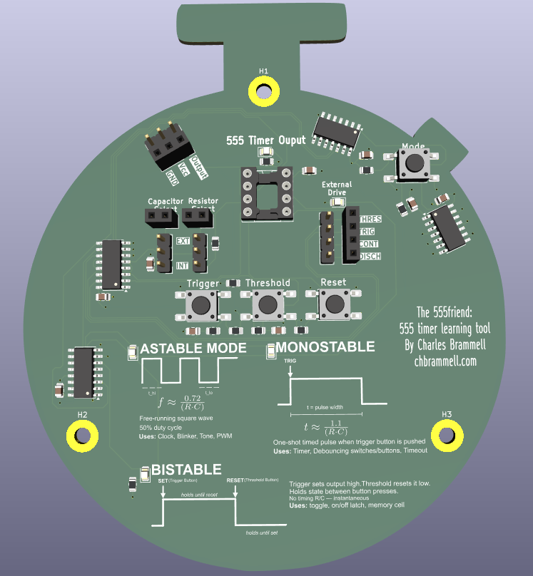

The 555friend lets you experiment with a real 555 timer (TLC555) across all of its classic configurations without rewiring anything. A single button cycles through the four modes. The board automatically reconfigures the 555's internal connections for the selected mode via an analog multiplexer, and a bank of LEDs tells you which mode is active. Jumper headers let you plug in different resistors and capacitors to change timing behavior on the fly.
Labeled waveform diagrams and formulas are silkscreened directly onto the board so you always have the reference right in front of you.
The 555 runs as a free-running square wave oscillator with no external trigger needed. The output continuously toggles between high and low at a frequency set by the RC network.
f ≈ 0.72 / (R·C) ~50% duty cycleUse cases: clocks, buzzers, tone generators, PWM signals, blinking LEDs.
The 555 produces a single timed pulse each time the trigger button is pressed. The output goes high for a fixed duration determined by the RC network, then returns low and waits for the next trigger.
t ≈ 1.1 × (R·C) (pulse width)Use cases: timers, switch debouncing, one-shot delays, timeout circuits.
No RC timing network is used. The trigger and threshold inputs act as SET and RESET. The output latches high when triggered and latches low when the threshold/reset button is pressed — it holds its state indefinitely between button presses.
Use cases: toggle switches, on/off latches, memory cells, debouncing mechanical contacts.
The 555's trigger, threshold, control, and discharge pins are broken out to a 4-pin header. This mode lets you drive the 555 from an external signal source for advanced experiments, or connect it to test equipment to probe the internal comparator behavior directly.
A push button (MODE_button1) increments a binary counter (4D24). The counter's two least-significant output bits (MODE_Select_0, MODE_Select_1) encode the current mode as a 2-bit value, giving four states (0–3) that map to the four operating modes.
MODE_Select_0 and MODE_Select_1 feed directly into the A/B select pins of a CD4052B dual 4-channel analog multiplexer. The mux is wired between the 555's TRIG, THRES, CONT, and DISCH pins and the RC network, so switching modes literally reroutes the electrical connections inside the 555 circuit without any rewiring required.
The same two mode select lines feed a 4555 binary-to-1-of-4 decoder. Each of its four outputs drives a dedicated mode indicator LED so the active mode is always visible at a glance.
Two sets of jumper headers (CONN_cap_select and CONN_res_select) let you choose from multiple capacitor and resistor values. Swap jumpers to change the timing constants and watch the output behavior change in real time.
The 555 output drives an indicator LED through a current-limiting resistor and is also brought out to a 2-pin header (555_OUT) so you can probe it with an oscilloscope or connect it to external circuitry.
| Feature | Details |
|---|---|
| 555 IC | TLC555xD |
| Mode selection | Push button + 4D24 binary counter |
| Mode routing | CD4052B dual analog multiplexer |
| Mode indication | 4555 decoder + 4 LEDs |
| RC selection | Jumper headers (3-position cap, 3-position res) |
| Output | LED indicator + 2-pin breakout header |
| External drive | 4-pin header (THRES, TRIG, CONT, DISCH) |
| Mounting | 3x M3 mounting holes |
| Form factor | Circular PCB, stopwatch-inspired shape |
555_demo/               KiCad schematic and PCB project
  pcbway_production/    Gerbers and production files
stopwatch_doc.png       PCB render
schematic_rev1.pdf Full schematic PDFDesigned by Charles Harrison Brammell — chbrammell.com
Hardware design files are open source. Feel free to build your own, modify the design, or use it as a teaching reference.
This README was written with the assistance of AI. All hardware design, schematic, and PCB work is original.
| Qty | Value | Footprint | References |
|---|---|---|---|
| 7 | 0.1u | Capacitor_SMD:C_0805_2012Metric | CAP_decoup_555, CAP_decoup_counter1, CAP_decoup_decoder1, CAP_decoup_mux1, CAP_decoup_strig1, CAP_filter_trig_button1, CAP_MODE_BUTTON1 |
| 6 | 10k | Resistor_SMD:R_0805_2012Metric | Filter_MODE_BUTTON1, Pulldown_THRES1, Pullup_COUNTER1, Pullup_RST1, Pullup_TRIG1, RESIS_filter_trig_button1 |
| 5 | LED | LED_SMD:LED_0805_2012Metric | LED_555_out1, LED_mode_0, LED_mode_1, LED_mode_2, LED_mode_3 |
| 4 | SW_Push | Button_Switch_SMD:SW_Push_1P1T_NO_E-Switch_TL3301NxxxxxG | MODE_button1, Reset, Threshold, Trigger |
| 3 | Conn_01x03_Pin | Connector_PinHeader_2.54mm:PinHeader_1x03_P2.54mm_Vertical | CONN_cap_select1, CONN_power_male1, CONN_resis_select1 |
| 3 | MountingHole | MountingHole:MountingHole_3.2mm_M3_Pad | H1, H2, H3 |
| 2 | 100k | Resistor_SMD:R_0805_2012Metric | RC_resis1, RESIS_filter_thres_button1 |
| 2 | 2.2k | Resistor_SMD:R_0805_2012Metric | RESIS_555_out_led1, RESIS_mode_led1 |
| 2 | Conn_01x02_Socket | Connector_PinSocket_2.54mm:PinSocket_1x02_P2.54mm_Vertical | CONN_ext_cap1, CONN_ext_resis1 |
| 1 | 10u | Capacitor_SMD:C_0805_2012Metric | RC_cap1 |
| 1 | 1u | Capacitor_SMD:C_0805_2012Metric | CAP_filter_thres_button1 |
| 1 | 40106 | Package_SO:SOIC-14_3.9x8.7mm_P1.27mm | U3 |
| 1 | 4024 | Package_SO:SOIC-14_3.9x8.7mm_P1.27mm | U4 |
| 1 | 4555 | Package_SO:SOIC-16_3.9x9.9mm_P1.27mm | U6 |
| 1 | CD4052B | Package_SO:SOIC-16_3.9x9.9mm_P1.27mm | U2 |
| 1 | Conn_01x03_Socket | Connector_PinSocket_2.54mm:PinSocket_1x03_P2.54mm_Vertical | CONN_power_female1 |
| 1 | Conn_01x04_Pin | Connector_PinHeader_2.54mm:PinHeader_1x04_P2.54mm_Vertical | CONN_ext_drive_male1 |
| 1 | Conn_01x04_Socket | Connector_PinSocket_2.54mm:PinSocket_1x04_P2.54mm_Vertical | CONN_ext_drive_female1 |
| 1 | TLC555xD | Package_DIP:DIP-8_W7.62mm_Socket | U1 |


qbancoffee/cocoplusplus
So now it's time to have fun.... I want to base this board on the CoCo 3 for several reasons.

qbancoffee/coco_daiquiri
A board that replaces the functionality of the SC77526 DAC chip in the Tandy CoCo's

tullulah/VectrexPCBRepro
OpenHardware project to reproduce the original PCB of the Vectrex (3GE Revision)

0BitsnBytes/McQueen
an overpowered rc car that poses a danger to my safety :)
It measures 97.9 × 113.9 mm and has 2 copper layers, 1.6 mm thick.
44 parts, built around the CD4052BM. The full list of its parts is on this page, with links to each part's symbol and footprint where PCBKit's library has them.
From the harrisoncbrammell/555friend repository on GitHub, at the commit this page was made from: the board is 555_demo/555_demo.kicad_pcb and its schematic 555_demo/555_demo.kicad_sch. PCBKit opens the board in the browser, with nothing to install.
Its repository states no licence, so its author keeps all rights: ask harrisoncbrammell before reusing the design.