2 layers280 × 155.3 mm
Coco3
qbancoffee/cocoplusplus
So now it's time to have fun.... I want to base this board on the CoCo 3 for several reasons.
211 parts9

 qbancoffee/coco_daiquiri7
A board that replaces the functionality of the SC77526 DAC chip in the Tandy CoCo's
Color computer dac is an open-source printed circuit board by qbancoffee, from the qbancoffee/coco_daiquiri repository on GitHub, published under the GPL-3.0 licence. It is a 2-layer board of 22.5 × 41.1 mm with 18 parts on 33 nets, routed with 517 tracks and 61 vias.
It is built around the 74LS367PC, CD4052BM and LM393, with the TS5A3166DBVR-TP among its other parts. Its parts include 12 resistors, 4 ICs, 1 capacitor and 1 connector. It belongs with the audio and music boards of this library.


A drop in replacement board for the SC77526P DAC chip found in the Tandy CoCo's
This board replaces the functionality of the SC77526P DAC chip found in the Tandy CoCo's. The DAC chip is one of the custom linear integrated circuits used in the Color Computer 2 and 3. As its name implies, it contains a Digital to Analog Converter. This chip also contains a sound multiplexer and the circuitry necessary to interface the joystick controllers to the microprocessor.
I designed it using available parts from JLCPCB to reduce assembly time and to bring down the cost.
All goals were met!!!
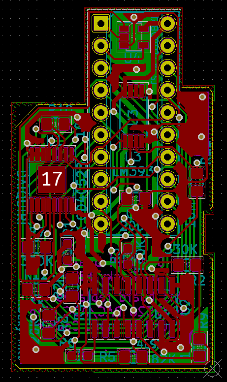
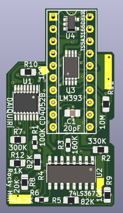
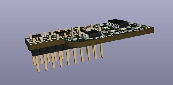
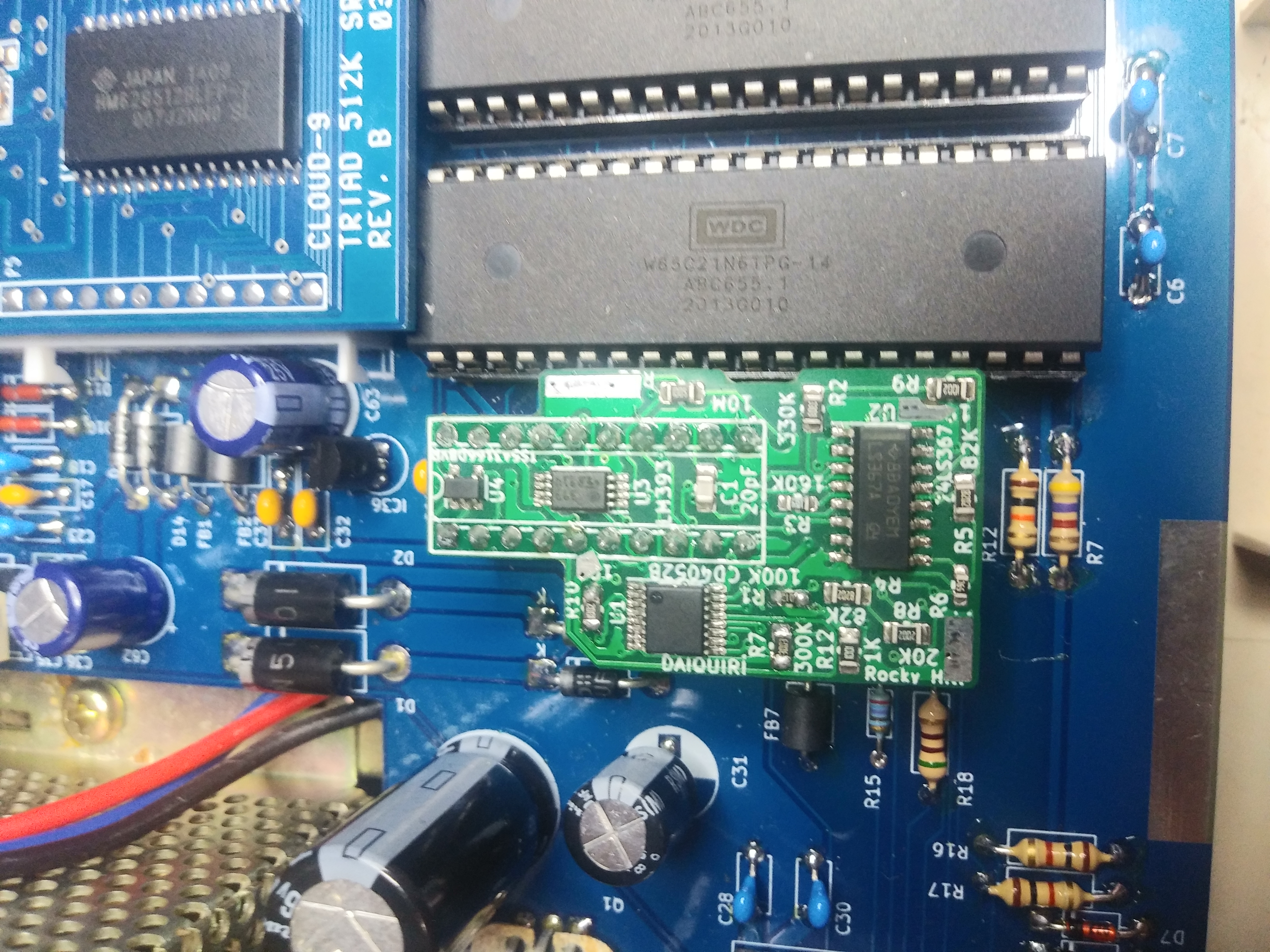
CoCo 3 with Daiquiri chip installed
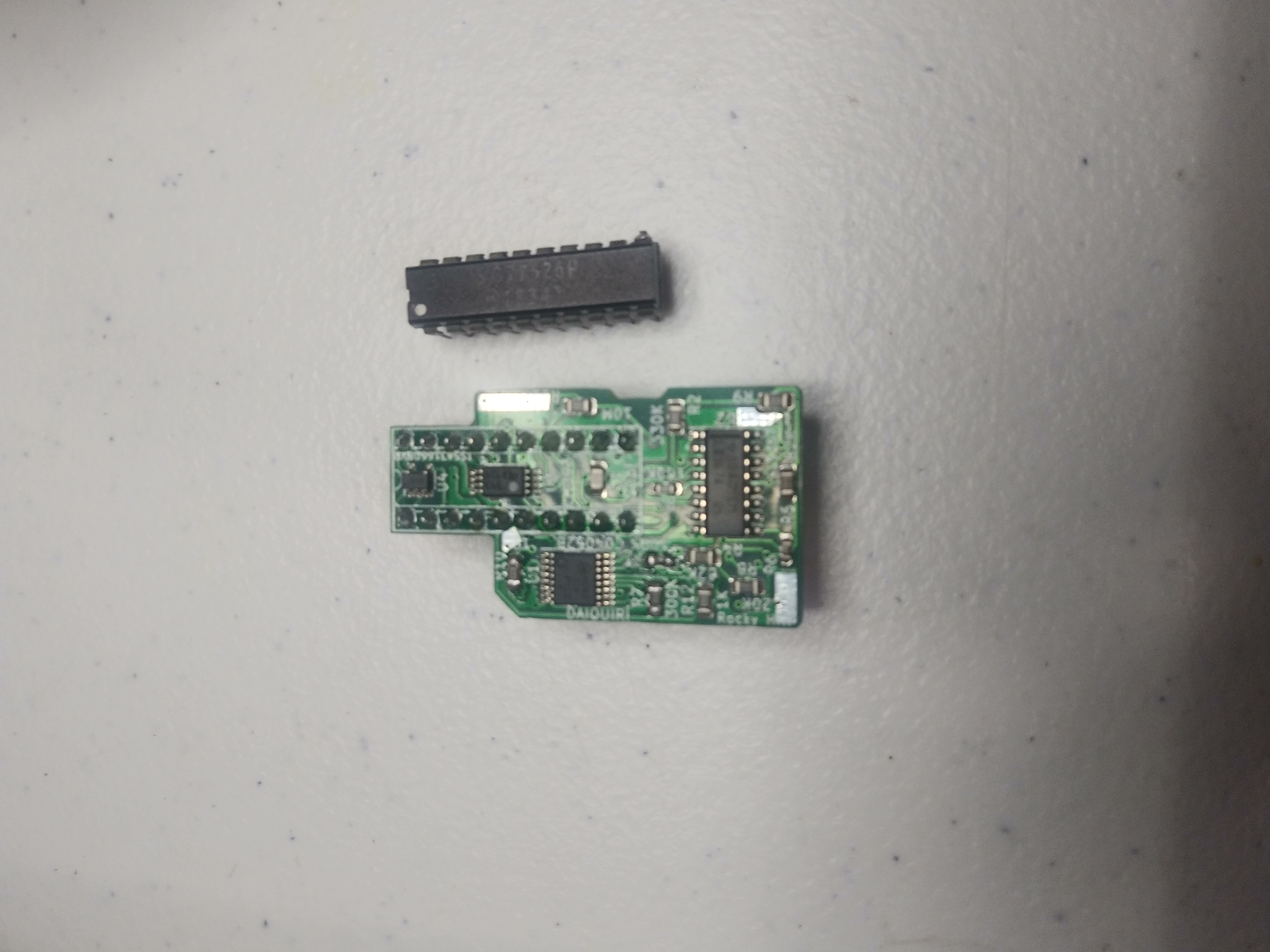
First Thing to do is clone this repository or download the latest release.
Many PCB manufacturers provide proprietary EDA software with nice and helpful features to help the user decrease the time and difficulty when designing a PCB. Unfortunately sometimes these programs will only allow you to order from that specific manufacturer. This is good for the manufacturer because it increases the odds that the person will order from them again because of the amount of time invested in learning to use that specific EDA program.
There are very nice EDA programs that will allow to design a PCB really quickly with fewer errors when it comes to components and footprints. Some of these programs are free to download and use for a trial period but after finishing your design sometimes you'll find that in order to export your design files so that you can actually order the boards you have to purchase a license. Sometimes you'll also find that there is a total area limit on the size of your design unless you buy a license. Companies use these tactics to make money and I really can't blame them because they have to make a living somehow.
I guess the question you might be asking is "Is there a specific PCB manufacturer I must use for a PCB designed with KiCAD?" The answer is no. PCB manufacturers will still take your business even if you've elected to use another piece of software for your design so long as you can provide the Gerber files for your design. The Gerber format is an open ASCII vector format for printed circuit board (PCB) designs. It is the de facto standard used by PCB industry software to describe the printed circuit board images: copper layers, solder mask, legend, drill data, etc.
KiCAD has a bit of learning curve to it but once you are familiar with its quirks you'll find that having no limits on size, layers, components ect for your design is really nice and worth your investment in time. Also, being completely free, having no vendor association, and having no licensing issues means that you can start using right it away without worries and when you're done just create the gerber files.
You can open the PCB design and create the gerber files yourself but I've already done that for the board so all you have to do is download the zip archive and upload it to your PCB manufacturer of choice. Click on the link below to download the gerber files.
There are a ton of PCB manufactures to choose from but recently I've been using JLPCB because the quality is good and they are well priced. JLPCB will even provide an automated online quote for pcb manufacturing and assembly. Once ordered they should arrive in the mail. Obviously you can use any PCB manufacturer you wish.
Some manufacturers also have assembly services with costs varying based on the number of components, packaging and size of the board. Surface mount components are difficult to solder onto a board by hand but are perfect for automated PCB assembly making it much cheaper when it comes to using an assembly service. I chose to design these boards using surface mount components from LCSC's inventory so that JLCPCB can mostly assemble them.
To order the components you'll need a Bill Of Materials or a BOM. I've included a BOM for the board in the repo and just like the gerber files, they will be in the repo once you download it. Click on the link below to download the BOM.
The BOM includes LCSC part numbers so you can order them from JLCPCB, manufacturer part numbers so can search for the parts sold by other vendors, and other nice pieces of information to help you along.
To assemble the board JLCPCB will need to know the part locations and orientations, this information is in the CPL file.
Go to jlcpcb and create an account if you don't have one.
Click on "Quote Now" and then click on "Add Gerber File"
Select "daiquiri_gerber.zip
Scroll down and select "Free SMT Assembly for your PCB order"
Select "Assemble Top side" and agree to the terms and conditions.
Click on "Add BOM" and select "color_computer_dac_1.1.0_BOM.csv"
Click on "Add CPL file" and select "color_computer_dac-all_1.1.0_POS.csv"
Click "Next" and go over the components and pricing.
Click "Next" or "Save to Cart".
If you like the price, order it and you should receive a mostly assembled board.
Beacuse they are through hole components you'll have to solder the pin headers yourself. However, I just found out that JLCPCB offers hand soldering services now so you may want to look into that.....
If you don't have 2.54 mm pitch breakaway pin headers laying around you can order from many places.
Here is a machine pin version which works better for the different type of sockets out there.
https://www.ebay.com/itm/155119535147
Thanks for the suggestion RETRO Innovations!
| Qty | Value | Footprint | References |
|---|---|---|---|
| 2 | 10K | Resistor_SMD:R_0805_2012Metric_Pad1.20x1.40mm_HandSolder | R9, R10 |
| 2 | 82K | Resistor_SMD:R_0805_2012Metric_Pad1.20x1.40mm_HandSolder | R4, R5 |
| 1 | 100K | Resistor_SMD:R_0603_1608Metric_Pad0.98x0.95mm_HandSolder | R1 |
| 1 | 10M | Resistor_SMD:R_0805_2012Metric_Pad1.20x1.40mm_HandSolder | R11 |
| 1 | 160K | Resistor_SMD:R_0603_1608Metric_Pad0.98x0.95mm_HandSolder | R3 |
| 1 | 1K | Resistor_SMD:R_0805_2012Metric_Pad1.20x1.40mm_HandSolder | R12 |
| 1 | 20K | Resistor_SMD:R_0805_2012Metric_Pad1.20x1.40mm_HandSolder | R8 |
| 1 | 20pF | Capacitor_SMD:C_0805_2012Metric_Pad1.18x1.45mm_HandSolder | C1 |
| 1 | 300K | Resistor_SMD:R_0805_2012Metric_Pad1.20x1.40mm_HandSolder | R7 |
| 1 | 330K | Resistor_SMD:R_0805_2012Metric_Pad1.20x1.40mm_HandSolder | R2 |
| 1 | 40.2K | Resistor_SMD:R_0603_1608Metric_Pad0.98x0.95mm_HandSolder | R6 |
| 1 | 74LS367 | Package_SO:SOIC-16_3.9x9.9mm_P1.27mm | U2 |
| 1 | CD4052B | Package_SO:HTSSOP-16-1EP_4.4x5mm_P0.65mm_EP3x3mm | U1 |
| 1 | Conn_02x10_Counter_Clockwise | Package_DIP:DIP-20_W7.62mm_Socket | J1 |
| 1 | LM393 | Package_SO:TSSOP-8_4.4x3mm_P0.65mm | U3 |
| 1 | TS5A3166DBVR | Package_TO_SOT_SMD:SOT-23-5 | U4 |
qbancoffee/cocoplusplus
So now it's time to have fun.... I want to base this board on the CoCo 3 for several reasons.


shreya2717/Solar-Rooftop-Financing-Market-Risk-Analysis
Solar energy is the cleanest and most available renewable energy source. The Modern technology can harness this energy for a variety of uses, including producing electricity, providing light and heating water for…


Morethanmany2/Arduino-Uno
As a part of my day-to-day use, i tried to design the Arduino UNO dev board using all the datasheet materials and footprints required for precise design.
It measures 22.5 × 41.1 mm and has 2 copper layers, 1.6 mm thick.
18 parts, built around the 74LS367PC, CD4052BM, LM393 and TS5A3166DBVR-TP. The full list of its parts is on this page, with links to each part's symbol and footprint where PCBKit's library has them.
From the qbancoffee/coco_daiquiri repository on GitHub, at the commit this page was made from: the board is color_computer_dac.kicad_pcb. PCBKit opens the board in the browser, with nothing to install.
Its repository publishes it under the GPL-3.0 licence: you may reuse it on that licence's terms (keep the author's notice, and for a copyleft licence share your changes alike).