2 layers56 × 78 mm

 hansliss/HexKeyboard1
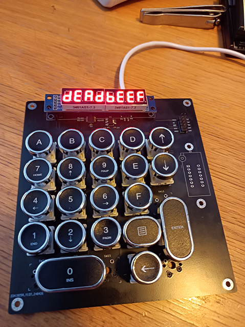
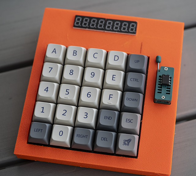
A 25 x 25 keypad with a LED display and many features.
HexKeyboard is an open-source printed circuit board by hansliss, from the hansliss/HexKeyboard repository on GitHub, published under the BSD-2-Clause licence. It is a 2-layer board of 132.2 × 144.1 mm with 83 parts on 85 nets, routed with 1,022 tracks and 58 vias.
It is built around the ATMEGA32U4-AU, 74LVC125AD and MAX7219M, with the AMS1117-3.3 and AT24CS64-XHM-B among its other parts. Its parts include 27 diodes, 25 switches, 7 capacitors, 7 resistors and 5 ICs. It belongs with the AVR (ATmega, ATtiny) boards of this library.


A 25 x 25 keypad with a LED display and many features.
The SD card holder is connected to SPI, plus
Note that CD is connected to the RXLED pin, so it will probably collide with serial data.
The display is connected like this:
This requires a local max7219.h with the defines modified. Just copy
If you want to eliminate problems with the two LED pins (see above), you can always just disable the entire functionality, by modifying USBCore.cpp (probably found here: C:\Users\Yourname\AppData\Local\Arduino15\packages\arduino\hardware\avr\1.8.6\cores\arduino).
Just comment out everything to do with RXLED and TXLED, and the file will be recompiled upon the next build.
The SPI pins for the MAX7219 display aren't actually SPI pins. Still, the max7219 library just bit-bangs the protocol so it doesn't really matter.
If you add an ESP-01/ESP-01S (with the Espressif "AT" firmware, for instance), set it to use 9600 baud on the serial interface. The default 115200 baud seems a bit too fast.
If you print the case, and want a LED indicator for the ESP-01, print out the included wifiSign model on a resin printer using transparent resin, then drill a 3.5mm hole roughly 3.7mm below the lower edge of the display and 13mm to the right of the right edge of the display, insert the transparent plug, and then pour black resin carefully around the symbol (preferably using a syringe and microscope) and cure it with a UV light.
| Qty | Value | Footprint | References |
|---|---|---|---|
| 25 | D | Diode_SMD:D_0603_1608Metric | D1, D2, D10, D11, D12, D13, D14, D15, D16, D17, D18, D19, D20, D21, D22, D23 +9 |
| 6 | MountingHole_Pad | MountingHole:MountingHole_3.2mm_M3_Pad_Via | H1, H2, H3, H4, H5, H6 |
| 3 | 100nF | Capacitor_SMD:C_0603_1608Metric | C1, C2, C4 |
| 3 | 3k3 | Resistor_SMD:R_0603_1608Metric | R1, R2, R3 |
| 2 | 22 | Resistor_SMD:R_0603_1608Metric | R4, R5 |
| 2 | 5k6 | Resistor_SMD:R_0603_1608Metric | R6, R7 |
| 2 | 9pF | Capacitor_SMD:C_0603_1608Metric | C5, C6 |
| 2 | BZX384-xxx | Diode_SMD:D_SOD-323 | D26, D27 |
| 1 | 10uF/10V | Capacitor_SMD:C_0805_2012Metric | C3 |
| 1 | 16MHz | Crystal:Crystal_SMD_2520-4Pin_2.5x2.0mm | Y1 |
| 1 | 1uF | Capacitor_SMD:C_0603_1608Metric | C7 |
| 1 | 74LVC125 | Package_SO:TSSOP-14_4.4x5mm_P0.65mm | U2 |
| 1 | AMS1117-3.3 | Package_TO_SOT_SMD:SOT-223-3_TabPin2 | U1 |
| 1 | AT24CS64-XHM | Socket:DIP_Socket-14_W4.3_W5.08_W7.62_W10.16_W10.9_3M_214-3339-00-0602J | U4 |
| 1 | ATmega32U4-AU | Package_QFP:TQFP-44_10x10mm_P0.8mm | U3 |
| 1 | Conn_01x04 | Connector_PinHeader_2.54mm:PinHeader_1x04_P2.54mm_Vertical | J2 |
| 1 | Conn_02x04_Odd_Even | Connector_PinHeader_2.54mm:PinHeader_2x05_P2.54mm_Vertical | J3 |
| 1 | Conn_02x04_Odd_Even | Connector_PinHeader_2.54mm:PinHeader_2x04_P2.54mm_Vertical | J4 |
| 1 | MAX7219 | MyFootprints:Display_x8_MAX7219 | U5 |
| 1 | Micro_SD_Card | MicroSD:GCT_MEM2075 | J1 |
| 1 | SW_1 | keyswitches:Kailh_socket_MX_optional_compatible | SW1 |
| 1 | SW_10 | keyswitches:Kailh_socket_MX_optional_compatible | SW10 |
| 1 | SW_11 | keyswitches:Kailh_socket_MX_optional_compatible | SW11 |
| 1 | SW_12 | keyswitches:Kailh_socket_MX_optional_compatible | SW12 |
| 1 | SW_13 | keyswitches:Kailh_socket_MX_optional_compatible | SW13 |
| 1 | SW_14 | keyswitches:Kailh_socket_MX_optional_compatible | SW14 |
| 1 | SW_15 | keyswitches:Kailh_socket_MX_optional_compatible | SW15 |
| 1 | SW_16 | keyswitches:Kailh_socket_MX_optional_compatible | SW16 |
| 1 | SW_17 | keyswitches:Kailh_socket_MX_optional_compatible | SW17 |
| 1 | SW_18 | keyswitches:Kailh_socket_MX_optional_compatible | SW18 |
| 1 | SW_19 | keyswitches:Kailh_socket_MX_optional_compatible | SW19 |
| 1 | SW_2 | keyswitches:Kailh_socket_MX_optional_compatible | SW2 |
| 1 | SW_20 | keyswitches:Kailh_socket_MX_optional_compatible | SW20 |
| 1 | SW_21 | keyswitches:Kailh_socket_MX_optional_compatible | SW21 |
| 1 | SW_22 | keyswitches:Kailh_socket_MX_optional_compatible | SW22 |
| 1 | SW_23 | keyswitches:Kailh_socket_MX_optional_compatible | SW23 |
| 1 | SW_24 | keyswitches:Kailh_socket_MX_optional_compatible | SW24 |
| 1 | SW_25 | keyswitches:Kailh_socket_MX_optional_compatible | SW25 |
| 1 | SW_3 | keyswitches:Kailh_socket_MX_optional_compatible | SW3 |
| 1 | SW_4 | keyswitches:Kailh_socket_MX_optional_compatible | SW4 |
| 1 | SW_5 | keyswitches:Kailh_socket_MX_optional_compatible | SW5 |
| 1 | SW_6 | keyswitches:Kailh_socket_MX_optional_compatible | SW6 |
| 1 | SW_7 | keyswitches:Kailh_socket_MX_optional_compatible | SW7 |
| 1 | SW_8 | keyswitches:Kailh_socket_MX_optional_compatible | SW8 |
| 1 | SW_9 | keyswitches:Kailh_socket_MX_optional_compatible | SW9 |
| 1 | USB_A | Connector_USB:USB_C_Receptacle_G-Switch_GT-USB-7010ASV | J5 |
It measures 132.2 × 144.1 mm and has 2 copper layers, 1.6 mm thick.
83 parts, built around the ATMEGA32U4-AU, 74LVC125AD, MAX7219M and AMS1117-3.3. The full list of its parts is on this page, with links to each part's symbol and footprint where PCBKit's library has them.
From the hansliss/HexKeyboard repository on GitHub, at the commit this page was made from: the board is HexKeyboard.kicad_pcb and its schematic HexKeyboard.kicad_sch. PCBKit opens the board in the browser, with nothing to install.
Its repository publishes it under the BSD-2-Clause licence: you may reuse it on that licence's terms (keep the author's notice, and for a copyleft licence share your changes alike).

uinika/UINIO-Logic-24MHz
the 24MHz sampling rate Logic Analyzer base on CY7C68013A.


CoreElectronics/CE-Makerverse-MicroSD-Card-Adapter
This is the repo for the Core Electronics Makerverse™ MicroSD Card Adapter.


kgl2001/Atom_Econet_AtoMMC
Combined AtoMMC & Econet interface board for Acorn Atom