4 layers42 × 65 mm
Icarus Flight Computer
daedalus-ind/icarus-hardware
Hardware of the onboard flight computer for the Icarus rocket.
106 parts2MIT

 h0lad/LoRaPowerBox8
The LoRaPowerBox combines the Heltec HT-CT62 module (ESP32C3 + Semtech SX1262) with a TI BQ25628E wide-range charger. Main target is IoT projects that deliver data over LoRa and/or Wifi utilizing solar power.
LoRaPowerBox is an open-source printed circuit board by h0lad, from the h0lad/LoRaPowerBox repository on GitHub, published under the CERN-OHL-S-2.0 licence. It is a 4-layer board of 51.6 × 60.6 mm with 54 parts on 45 nets, routed with 314 tracks and 193 vias.
It is built around the TPS631000DRL, APX803L05-29W and SSSS811101, with the TS-1088-AR02016 among its other parts. Its parts include 15 resistors, 13 capacitors, 12 connectors, 4 ICs and 3 diodes. It belongs with the power and radio and wireless boards and the ESP32 boards of this library.


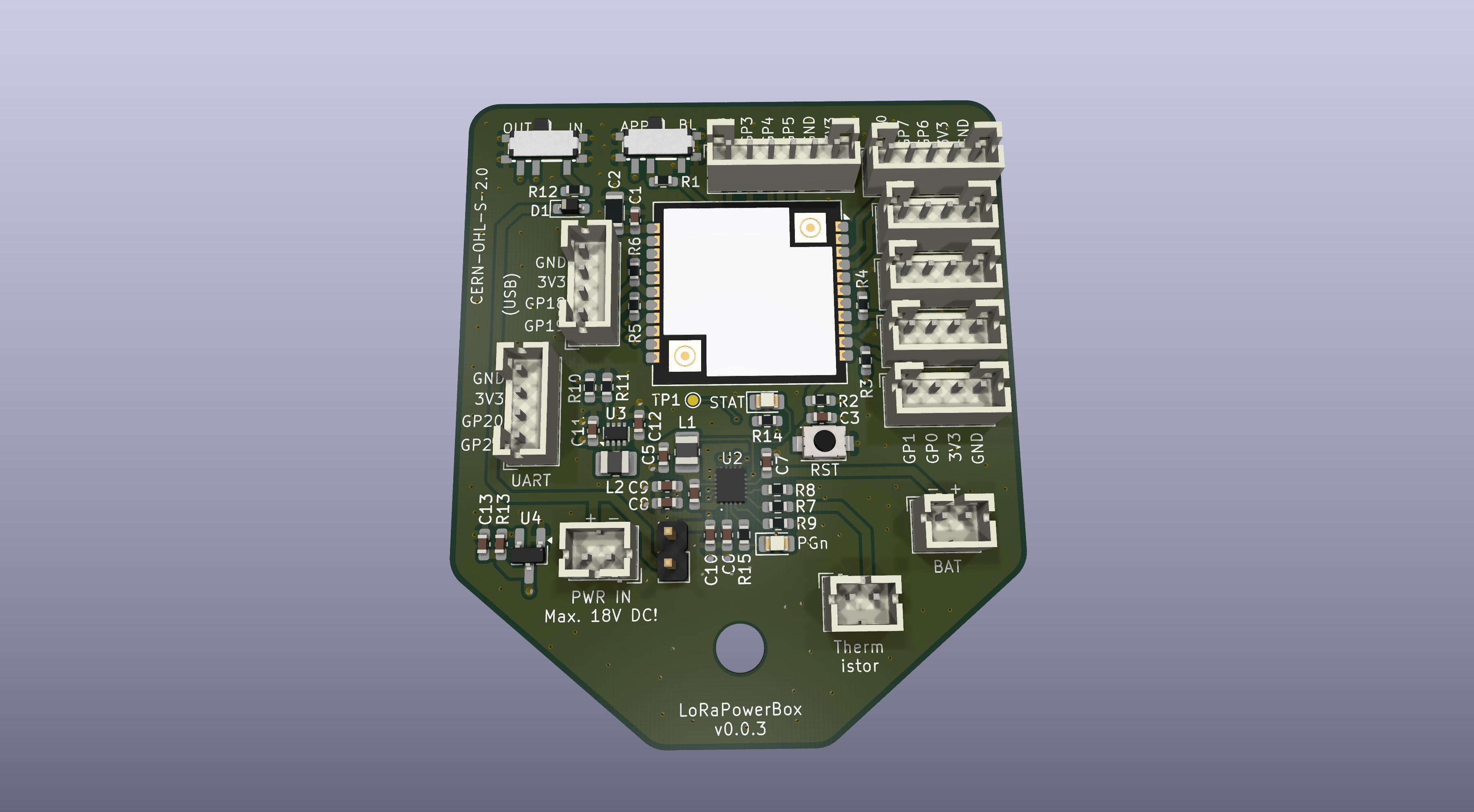
This PCB integrates a Heltec HT-CT62 (ESP32-C3 + SX1262), a TI BQ25628E wide-range Li-ion charger and a TI TPS631000 buck-boost converter providing a stable 3.3V rail at up to 1.5A. The TI BQ25628E is capable of handling highly dynamic sources like solar cells and wind generators.
You can see this project as a successor of the SolarMeshtasticNode project which was a reliable work horse - but showed several limitations. Improvements:
The size of the PCB is 60mm x 51mm and is planned (= screw hole fits into housing) around following Box (120x90x70).
Do not use the transparent version: it will heat up.
Simulation of the EdgeCut with a 1:1 print
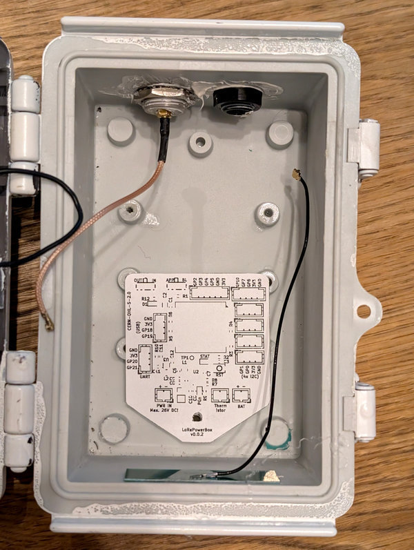
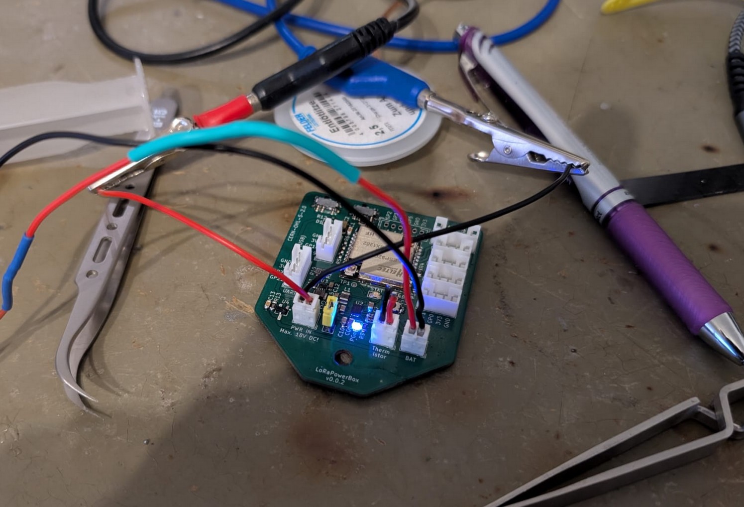
✅ Charging IC charges LiPo and blinks LED according to status
✅ Buck-Boost DCDC creates 3.3V
✅ Heating the thermistor forces throtteling of charging current
✅ Reset IC disables 3.3V using EN pin from DCDC if VBat falls below 3.2V
I also do a lot of data gathering into TSDBs via Wifi. The Espressif has the most comfortable stack for doing this.
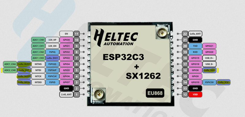
The Semtech SX1262 consumes a significant number of GPIOs.
Available pins If LoRa is being used: GPIO0, GPIO1, GPIO18, GPIO19, GPIO20, GPIO21
Note that GPIO8 and GPIO9 are strapping pins and are sampled during early boot.
If the SX1262 is not used, it can be disabled via its CS line (GPIO8) from application code.
| Qty | Value | Footprint | References |
|---|---|---|---|
| 6 | Conn_01x04_Pin | Connector_JST:JST_PH_B4B-PH-K_1x04_P2.00mm_Vertical | J1, J2, J3, J5, J6, J7 |
| 4 | 10k | Resistor_SMD:R_0603_1608Metric_Pad0.98x0.95mm_HandSolder | R1, R2, R5, R6 |
| 3 | Conn_01x02_Pin | Connector_JST:JST_PH_B2B-PH-K_1x02_P2.00mm_Vertical | J9, J10, J11 |
| 2 | 0.1uF | Capacitor_SMD:C_0603_1608Metric_Pad1.08x0.95mm_HandSolder | C1, C8 |
| 2 | 100nF | Capacitor_SMD:C_0603_1608Metric_Pad1.08x0.95mm_HandSolder | C3, C13 |
| 2 | 10uF | Capacitor_SMD:C_0603_1608Metric_Pad1.08x0.95mm_HandSolder | C7, C9 |
| 2 | 1uH | Inductor_SMD:L_1008_2520Metric_Pad1.43x2.20mm_HandSolder | L1, L2 |
| 2 | 300 | Resistor_SMD:R_0603_1608Metric_Pad0.98x0.95mm_HandSolder | R14, R15 |
| 2 | LED | LED_SMD:LED_0805_2012Metric_Pad1.15x1.40mm_HandSolder | D2, D3 |
| 2 | R | Resistor_SMD:R_0603_1608Metric_Pad0.98x0.95mm_HandSolder | R3, R4 |
| 2 | SSSS811101 | library:SW-SMD_SSSS811101 | SW1, SW3 |
| 1 | 1.5k | Resistor_SMD:R_0603_1608Metric_Pad0.98x0.95mm_HandSolder | R9 |
| 1 | 100k | Capacitor_SMD:C_0603_1608Metric_Pad1.08x0.95mm_HandSolder | R13 |
| 1 | 1uF | Capacitor_SMD:C_0603_1608Metric_Pad1.08x0.95mm_HandSolder | C10 |
| 1 | 20uF | Capacitor_SMD:C_0603_1608Metric_Pad1.08x0.95mm_HandSolder | C5 |
| 1 | 22uF | Capacitor_SMD:C_0603_1608Metric_Pad1.08x0.95mm_HandSolder | C12 |
| 1 | 30.1k | Resistor_SMD:R_0603_1608Metric_Pad0.98x0.95mm_HandSolder | R8 |
| 1 | 4.7uF | Capacitor_SMD:C_0603_1608Metric_Pad1.08x0.95mm_HandSolder | C6 |
| 1 | 47nF | Capacitor_SMD:C_0603_1608Metric_Pad1.08x0.95mm_HandSolder | C4 |
| 1 | 47uF | Resistor_SMD:R_1206_3216Metric_Pad1.30x1.75mm_HandSolder | C2 |
| 1 | 47uF | Capacitor_SMD:C_0603_1608Metric_Pad1.08x0.95mm_HandSolder | C11 |
| 1 | 5.23k | Resistor_SMD:R_0603_1608Metric_Pad0.98x0.95mm_HandSolder | R7 |
| 1 | 50 | Resistor_SMD:R_0603_1608Metric_Pad0.98x0.95mm_HandSolder | R12 |
| 1 | 511k | Resistor_SMD:R_0603_1608Metric_Pad0.98x0.95mm_HandSolder | R10 |
| 1 | 91k | Resistor_SMD:R_0603_1608Metric_Pad0.98x0.95mm_HandSolder | R11 |
| 1 | APX803L05 | Package_TO_SOT_SMD:SOT-23_Handsoldering | U4 |
| 1 | Conn_01x02_Pin | Connector_PinHeader_2.54mm:PinHeader_1x02_P2.54mm_Vertical | J8 |
| 1 | Conn_01x05_Pin | Connector_JST:JST_PH_B5B-PH-K_1x05_P2.00mm_Vertical | J12 |
| 1 | Conn_01x06_Pin | Connector_JST:JST_PH_B6B-PH-K_1x06_P2.00mm_Vertical | J4 |
| 1 | D | Diode_SMD:D_SOD-323_HandSoldering | D1 |
| 1 | HT-CT62 | RF_Module:Heltec_HT-CT62 | U1 |
| 1 | MountingHole | MountingHole:MountingHole_4.3mm_M4_DIN965 | H1 |
| 1 | TI BQ25628E | library:BQ25622ERYKR | U2 |
| 1 | TPS631000 | Package_TO_SOT_SMD:SOT-583-8 | U3 |
| 1 | TS-1088-AR02016 | library:SW-SMD_L3.9-W3.0-P4.45 | SW2 |
| 1 | TestPoint | TestPoint:TestPoint_Pad_D1.0mm | TP1 |
It measures 51.6 × 60.6 mm and has 4 copper layers, 1.6 mm thick.
54 parts, built around the TPS631000DRL, APX803L05-29W, SSSS811101 and TS-1088-AR02016. The full list of its parts is on this page, with links to each part's symbol and footprint where PCBKit's library has them.
From the h0lad/LoRaPowerBox repository on GitHub, at the commit this page was made from: the board is pcb/LoraPowerBox.kicad_pcb and its schematic pcb/LoraPowerBox.kicad_sch. PCBKit opens the board in the browser, with nothing to install.
Its repository publishes it under the CERN-OHL-S-2.0 licence: you may reuse it on that licence's terms (keep the author's notice, and for a copyleft licence share your changes alike).
daedalus-ind/icarus-hardware
Hardware of the onboard flight computer for the Icarus rocket.

JohnNeville/SunSprout
An esp32-c5 powered board that adds dual source battery charging, fuel management, and differential i2c bus. This was largely developed to be a complement with my other soil sensor project.

h0lad/LoRaHarvesterBox
PCB integrating a ST STM32WLE5CC and TI BQ25570 energy harvester. Ideal platform for ultra-low-power LoRa(WAN) nodes projects.

tangles-0/cyberdeck-scout
// #ifndef PINPA0 // #define PINPA0 11 // #endif // #ifndef PINPA1 // #define PINPA1 8 // #endif // #ifndef PINPA2 // #define PINPA2 9 // #endif // #ifndef PINPA3 // #define PINPA3 10 // #endif // #ifndef PINPA4 //…


jernej13/Tempic
Small solarpowered ESP32 based indoor/outdoor wifi weather station.
