Skip to the content
PCBKitNew board
2 layers50 × 35 mmBms4 f051, the printed circuit board in 3D

Battery management system (bms) for 4 series Li-Ion cells programmed in Rust

Size
50 × 35 mm
Copper layers
2
Thickness
1.6 mm
Parts
63
Nets
59
Pads
203
Tracks, vias
650, 41
Pours
1
Routed
Yes
KiCad
KiCad 7 (file 20221018)
Created
8 Nov 2023
Updated
20 Nov 2023

Overview

Bms4 f051 is an open-source printed circuit board by GyrocopterLLC, from the GyrocopterLLC/bms4-rust repository on GitHub, published under the MIT licence. It is a 2-layer board of 50 × 35 mm with 63 parts on 59 nets, routed with 650 tracks and 41 vias.

It is built around the OPA2171AID, ISO7721D and DCX114YU, with the LTST-C155GEKT among its other parts. Its parts include 27 resistors, 12 capacitors, 8 transistors, 5 ICs and 5 connectors. It belongs with the power boards and the STM32 boards of this library.

Main components

4

README

hardware/README.md

bms4_f051 Hardware Design Files

Designed in Kicad 7.0
https://www.kicad.org/

Board Notes

Based on STM32F051K8 microcontroller.
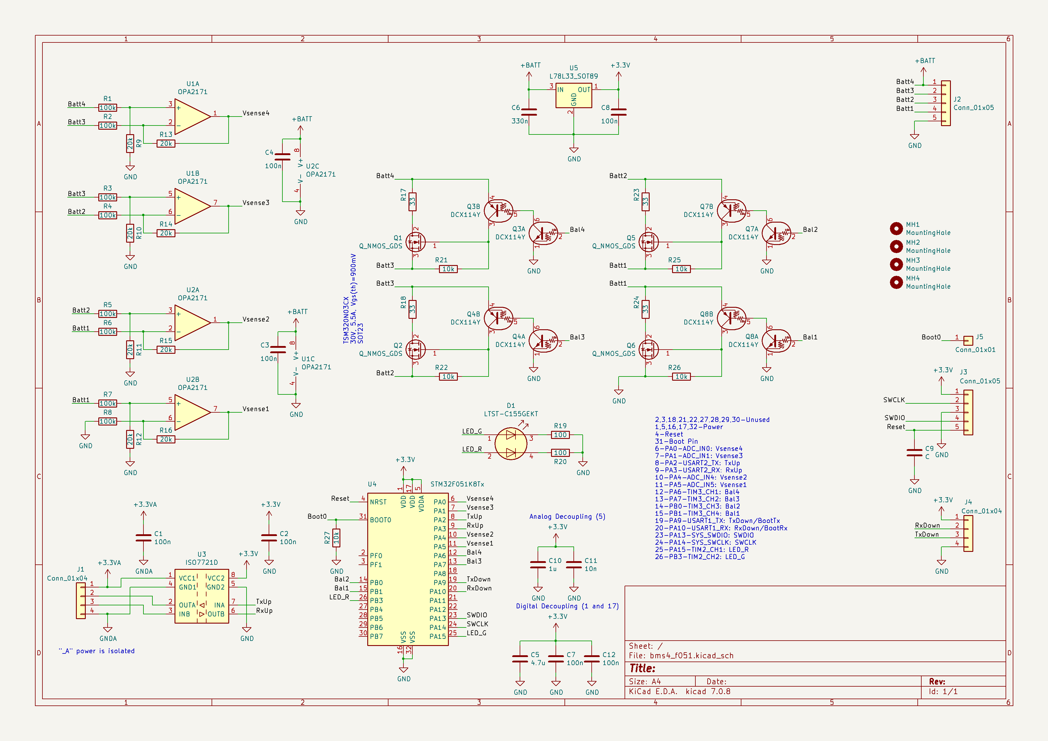
Uses 2x dual LM2904 op-amps to measure the voltage of the lithium ion batteries. Stepping down the voltage is necessary to avoid damaging the microcontroller's input pins which are limited to 3.3V. Balancing is performed by 33 ohm shunt resistors, one per cell. The are turned on by the microcontroller through external FETs (AO3400A). Communication is done through an isolation circuit (ISO7221D). This is used to be able to communicate to other bms4_f051 boards in a series battery configuration. In series, the boards will not share grounds. Connecting one board's ground to another board's ground would create a dangerous short circuit through the LiIon batteries! The boards are designed to be daisy-chained in communication, with the bottom-most (or top-most, your choice) board connected to an external controller, for example an ebike motor controller.

Board Images
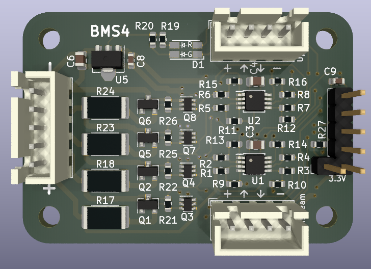
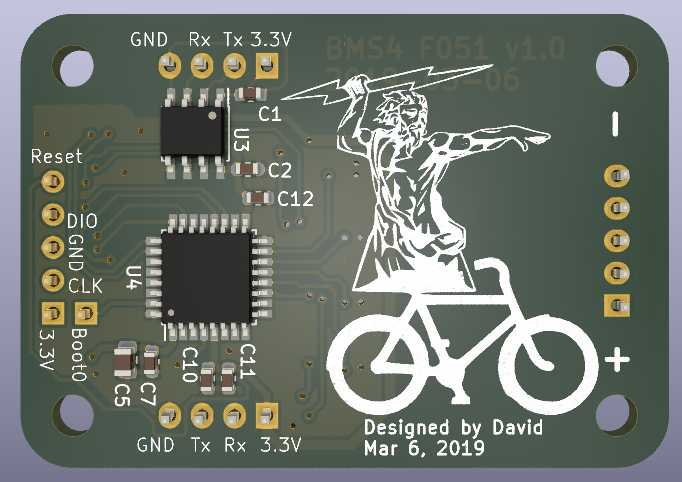
Board Top Board Bottom Schematic

Parts

63
QtyValueFootprintReferences
8100kResistor_SMD:R_0603_1608MetricR1, R2, R3, R4, R5, R6, R7, R8
820kResistor_SMD:R_0603_1608MetricR9, R10, R11, R12, R13, R14, R15, R16
7100nCapacitor_SMD:C_0603_1608MetricC1, C2, C7, C8, C10, C11, C12
510kResistor_SMD:R_0603_1608MetricR21, R22, R25, R26, R27
433Resistor_SMD:R_2512_6332MetricR17, R18, R23, R24
4DCX114YPackage_TO_SOT_SMD:SOT-363_SC-70-6Q3, Q4, Q7, Q8
4MountingHoleMountingHole:MountingHole_3.2mm_M3MH1, MH2, MH3, MH4
4Q_NMOS_GDSPackage_TO_SOT_SMD:SOT-23Q1, Q2, Q5, Q6
2100Resistor_SMD:R_0603_1608MetricR19, R20
2100nCapacitor_SMD:C_0805_2012MetricC3, C4
2Conn_01x04Connector_JST:JST_XH_B04B-XH-A_1x04_P2.50mm_VerticalJ1, J4
2OPA2171Package_SO:TSSOP-8_3x3mm_P0.65mmU1, U2
1330nCapacitor_SMD:C_0805_2012MetricC6
14.7uCapacitor_SMD:C_0805_2012MetricC5
1CCapacitor_SMD:C_0603_1608MetricC9
1Conn_01x01Connector_PinHeader_2.54mm:PinHeader_1x01_P2.54mm_VerticalJ5
1Conn_01x05Connector_PinHeader_2.54mm:PinHeader_1x05_P2.54mm_VerticalJ3
1Conn_01x05Connector_JST:JST_XH_B05B-XH-A_1x05_P2.50mm_VerticalJ2
1ISO7721DPackage_SO:SOIC-8_3.9x4.9mm_P1.27mmU3
1L78L33_SOT89Package_TO_SOT_SMD:SOT-89-3U5
1LOGOLogos:zeusbikeG***
1LTST-C155GEKTCustom:LTST-C155GEKTD1
1STM32F051K8TxPackage_QFP:LQFP-32_7x7mm_P0.8mmU4

Questions

How big is the Bms4 f051 PCB?

It measures 50 × 35 mm and has 2 copper layers, 1.6 mm thick.

What parts does the Bms4 f051 use?

63 parts, built around the OPA2171AID, ISO7721D, DCX114YU and LTST-C155GEKT. The full list of its parts is on this page, with links to each part's symbol and footprint where PCBKit's library has them.

Where can I download the Bms4 f051 KiCad files?

From the GyrocopterLLC/bms4-rust repository on GitHub, at the commit this page was made from: the board is hardware/bms4_f051.kicad_pcb and its schematic hardware/bms4_f051.kicad_sch. PCBKit opens the board in the browser, with nothing to install.

Can I use the Bms4 f051 design in my own project?

Its repository publishes it under the MIT licence: you may reuse it on that licence's terms (keep the author's notice, and for a copyleft licence share your changes alike).

Similar boards

  • 2 layers70 × 76 mmControl, the printed circuit board in 3D

    Control

    Jochen0x90h/RoomControl

    Smart home room controller based on nRF52840 with MQTT and and IEEE 802.15.4 radio support. Buttons and relays for lights and roller shutters can also be connected with a local bus using LIN physical layer

    79 parts3
  • 2 layers104 × 76 mmSdc ntc emulator, the printed circuit board in 3D

    Sdc ntc emulator

    bl1ndc4m3l/sdc-ntc-emulator

    SDC3-40 NTC emulator for remote temperature setpoint

    58 parts
  • 2 layers38.7 × 106.7 mmPeaks v30, the printed circuit board in 3D

    Peaks v30

    mort13/clandestine_circuitry

    Collection of diy synth projects

    91 parts12GPL-3.0
  • 4 layers100 × 100 mmAmod b, the printed circuit board in 3D

    Amod b

    gallicchio/AMOD-and-RFMOD

    The tutorial's 2x12 adapter (/mudd/133electronics/icepi-zero-dac-adc/adapterboard/) with a 2 x 6 right-angle Pmod socket on a 15 mm extension of its right-hand end, so an Icepi Zero can drive AMOD-A's and RF-MOD's Pmod…

    147 parts
  • 2 layers100 × 28.6 mmApex3, the printed circuit board in 3D

    Apex3

    rhinocerose/eurorack-designs

    86 parts
  • 6 layers40 × 15 mmMiniDAQ, the printed circuit board in 3D

    MiniDAQ

    Aharoni-Lab/MiniDAQ

    Simplified bare bones DAQ for Miniscopes and Minicams

    162 parts
  • 2 layers80 × 58 mmEnergyReplay, the printed circuit board in 3D

    EnergyReplay

    FoRTE-Research/EnergyReplay

    HW/SW for energy replay

    57 parts
  • 2 layers74.9 × 55.9 mm6s 750mA, the printed circuit board in 3D

    6s 750mA

    jsarrett/StackedCharger

    Isolated stackable LiPo charger

    121 parts