2 layers60 × 30 mm
Controller
google/mozc-devices
Circuit diagrams and firmware source code for Gboard DIY keyboards
11 parts3kApache-2.0

 grimsteel/clock1
(temp name): Working 4-person HP Weasley Clock | Uses Home Assistant location information
Clock is an open-source printed circuit board by grimsteel, from the grimsteel/clock repository on GitHub, published under the GPL-3.0 licence. It is a 2-layer board of 34.8 × 24 mm with 11 parts on 25 nets, routed with 48 tracks and 1 via.
Its parts include 4 connectors, 2 resistors, 2 diodes and 1 IC. It belongs with the lEDs and displays boards and the ESP32 and RISC-V boards of this library.
Working 4-person location clock. Uses Home Assistant location zone information.

cad/ folder for a parts list and Onshape link)firmware/README.md)More information can be found in the cad/ folder. The clock consists of a laser cut front and back frame.
Each hand is controlled by a servo with a 2:1 gear ratio. The servos and gears are mouted on a 3d-printed frame, which is fastened to the back frame.
The hands are attached to four concentric shafs, each terminating at a different height. This is part of the reason the clock is so thick.
The front includes 4 possible mounting spots for LEDs.
The PCB consists of a surface mounted ESP32 C3 Supermini with connections for the 4 servos and 2 LEDs:
| Schematic | 3D render |
|---|---|
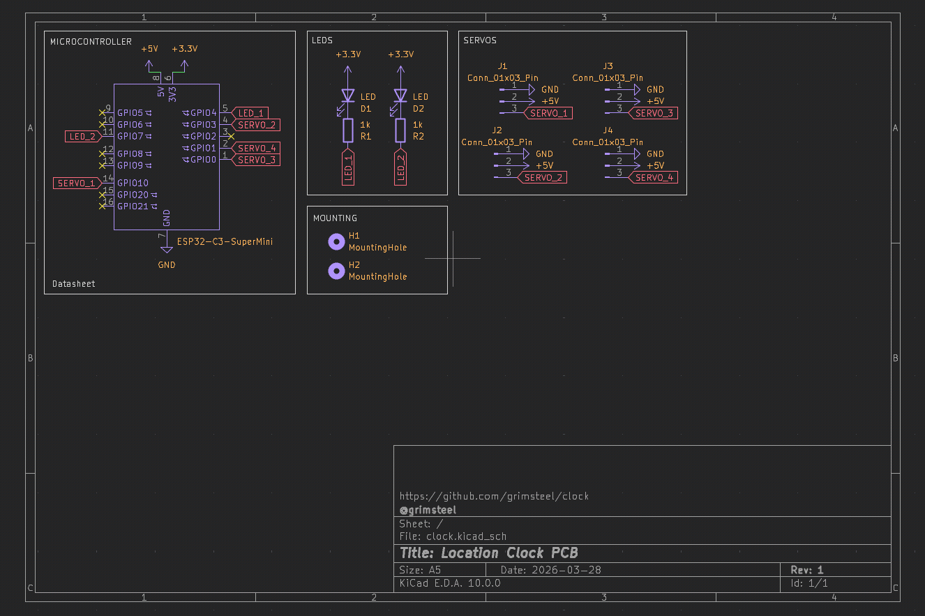 | 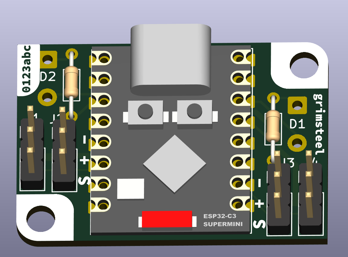 |
| Front | Back |
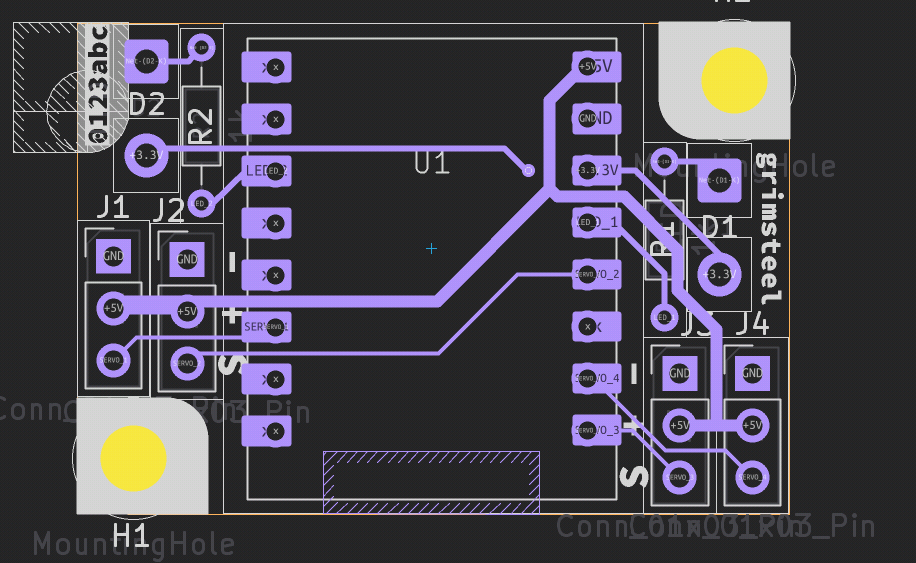 | 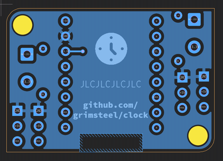 |
Two firmwares are provided: an ESPHome and a native ESP-IDF firmware. More information can be found in the firmware/ folder.
| Description | Link | Per-unit price | Quantity | Total price | Running price w/ tax |
|---|---|---|---|---|---|
| CAD components | https://cad.onshape.com/documents/5b8ef3e45edb03dc1124a4e9 | $0.00 | 1 | $0.00 | $0.00 |
| PCB | https://oshpark.com | $6.45 | 1 | $6.45 | $7.01 |
| ESP32-C3 Supermini | https://www.aliexpress.us/item/3256807292829704.html | $2.70 | 1 | $2.70 | $9.94 |
| MG90s Micro Servo (5 pack) | https://www.aliexpress.us/item/3256808303872992.html | $9.88 | 1 | $9.88 | $20.68 |
| Qty | Value | Footprint | References |
|---|---|---|---|
| 4 | Conn_01x03_Pin | Connector_PinHeader_2.54mm:PinHeader_1x03_P2.54mm_Vertical | J1, J2, J3, J4 |
| 2 | 1k | Resistor_THT:R_Axial_DIN0204_L3.6mm_D1.6mm_P7.62mm_Horizontal | R1, R2 |
| 2 | LED | Connector_Wire:SolderWire-0.5sqmm_1x02_P4.6mm_D0.9mm_OD2.1mm | D1, D2 |
| 2 | MountingHole | MountingHole:MountingHole_3.2mm_M3 | H1, H2 |
| 1 | ESP32-C3-SuperMini | custom:ESP32-C3-SuperMini | U1 |
It measures 34.8 × 24 mm and has 2 copper layers, 1.6 mm thick.
11 parts. The full list of its parts is on this page, with links to each part's symbol and footprint where PCBKit's library has them.
From the grimsteel/clock repository on GitHub, at the commit this page was made from: the board is pcb/clock.kicad_pcb and its schematic pcb/clock.kicad_sch. PCBKit opens the board in the browser, with nothing to install.
Its repository publishes it under the GPL-3.0 licence: you may reuse it on that licence's terms (keep the author's notice, and for a copyleft licence share your changes alike).
google/mozc-devices
Circuit diagrams and firmware source code for Gboard DIY keyboards


FrameworkComputer/ExpansionCards
Reference designs and documentation to create Expansion Cards for the Framework Laptop

hoglet67/RGBtoHDMI
Bare-metal Raspberry Pi project that provides pixel-perfect sampling of Retro Computer RGB/YUV video and conversion to HDMI

hackclub/OnBoard
💡 Join 1,000 teenagers and make your first PCB with a $100 grant!


tardate/LittleArduinoProjects
a collection of "Little Electronic & Arduino Projects", most involving electronics or an Arduino in one way or another!

basilfx/TRADFRI-Hacking
Hacking IKEA TRÅDFRI products, such as light bulbs, window blinds and other accessories.