2 layers100 × 100 mm

 Grehasopt/Electra-pcb2
Remote Relays Board
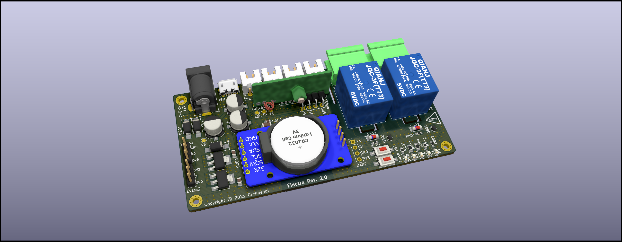
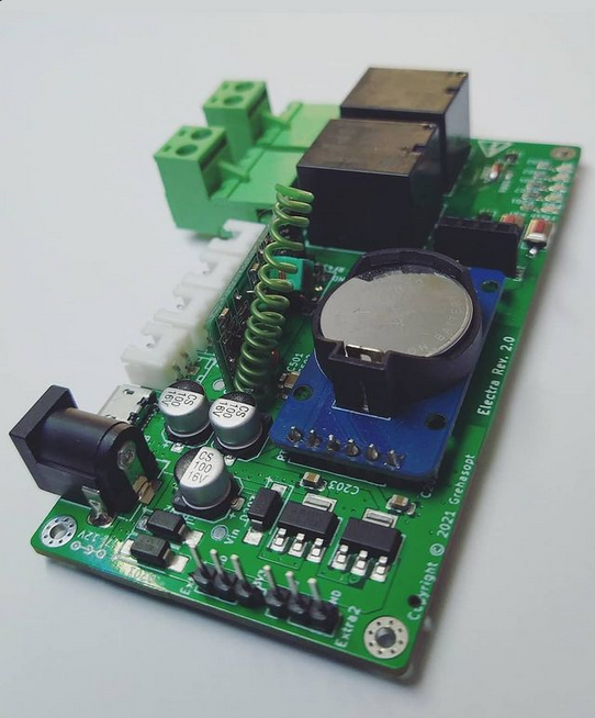
Electra is an open-source printed circuit board by Grehasopt, from the Grehasopt/Electra-pcb repository on GitHub, published under the CERN-OHL-S-2.0 licence. It is a 2-layer board of 100 × 48.5 mm with 77 parts on 52 nets, routed with 506 tracks and 292 vias.
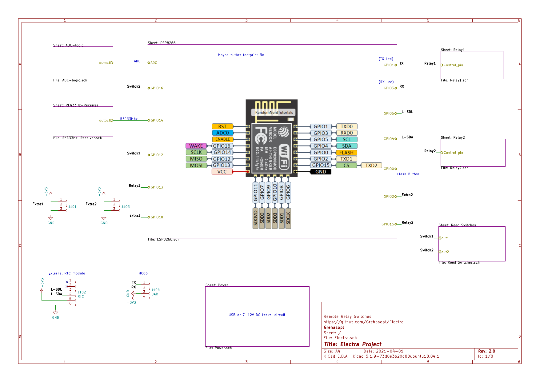
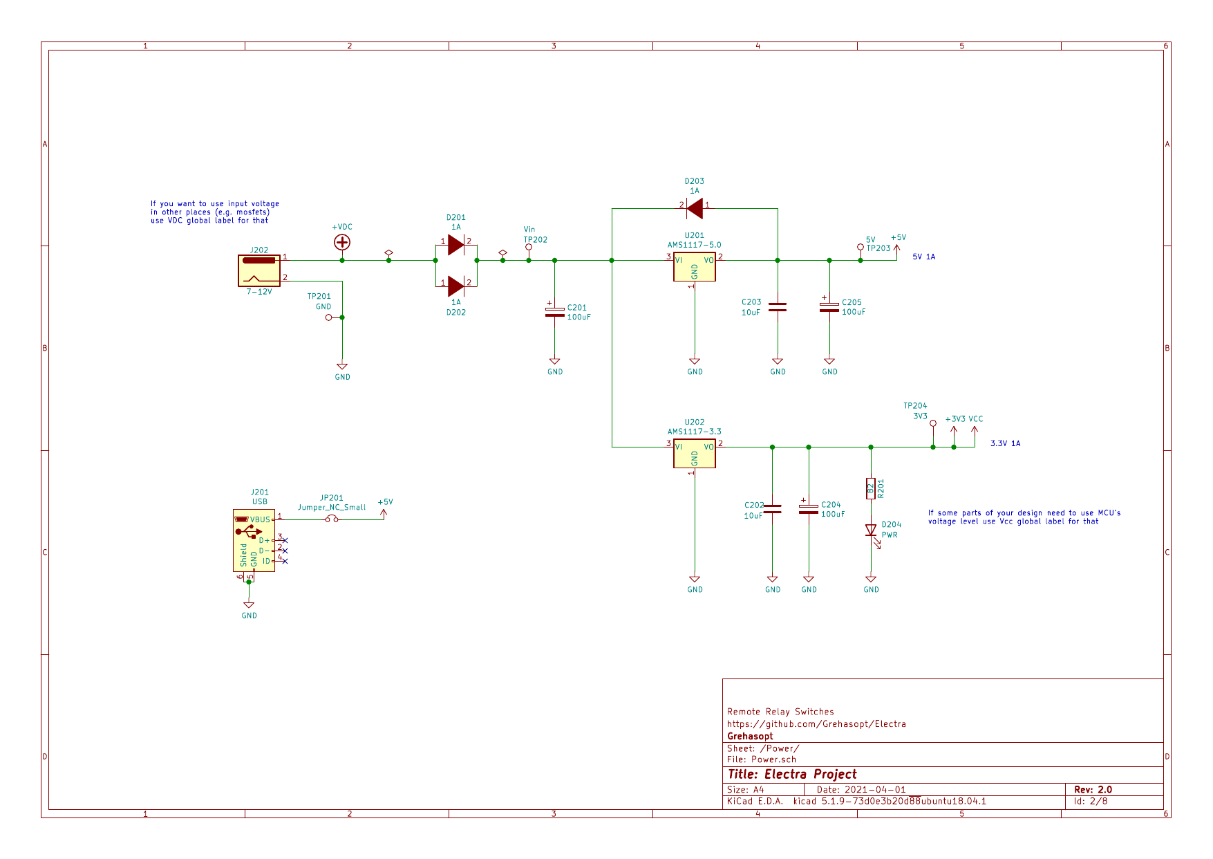
It is built around the ESP-12F, AMS1117-3.3 and AMS1117-5.0. Its parts include 19 resistors, 13 connectors, 10 diodes, 7 capacitors and 4 switches. It belongs with the ESP8266 boards of this library.


Remote Relays Board
[!CAUTION]
This project involves the use of 230V AC mains power and contains high-voltage components. Working with mains electricity can be extremely dangerous and may result in serious injury, death, or property damage if not handled correctly.
This design is provided "as-is" and for educational purposes only. Only individuals with the appropriate electrical expertise and experience should attempt to reproduce or work with this project. You are solely responsible for ensuring that your work with this hardware complies with all applicable safety standards, laws, and regulations.
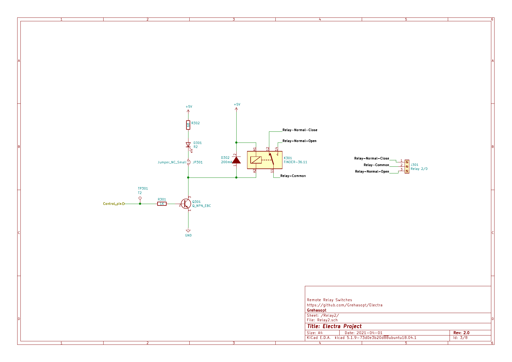
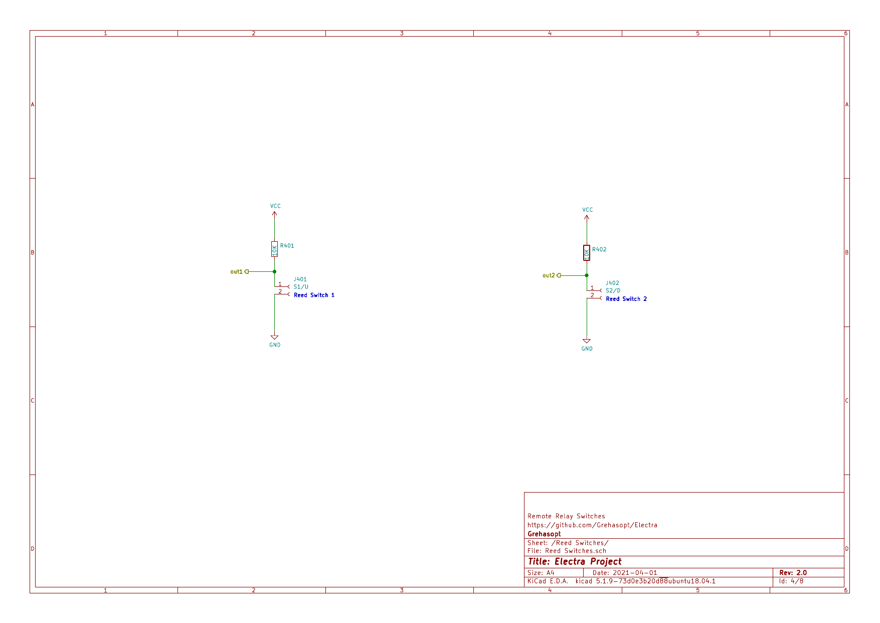
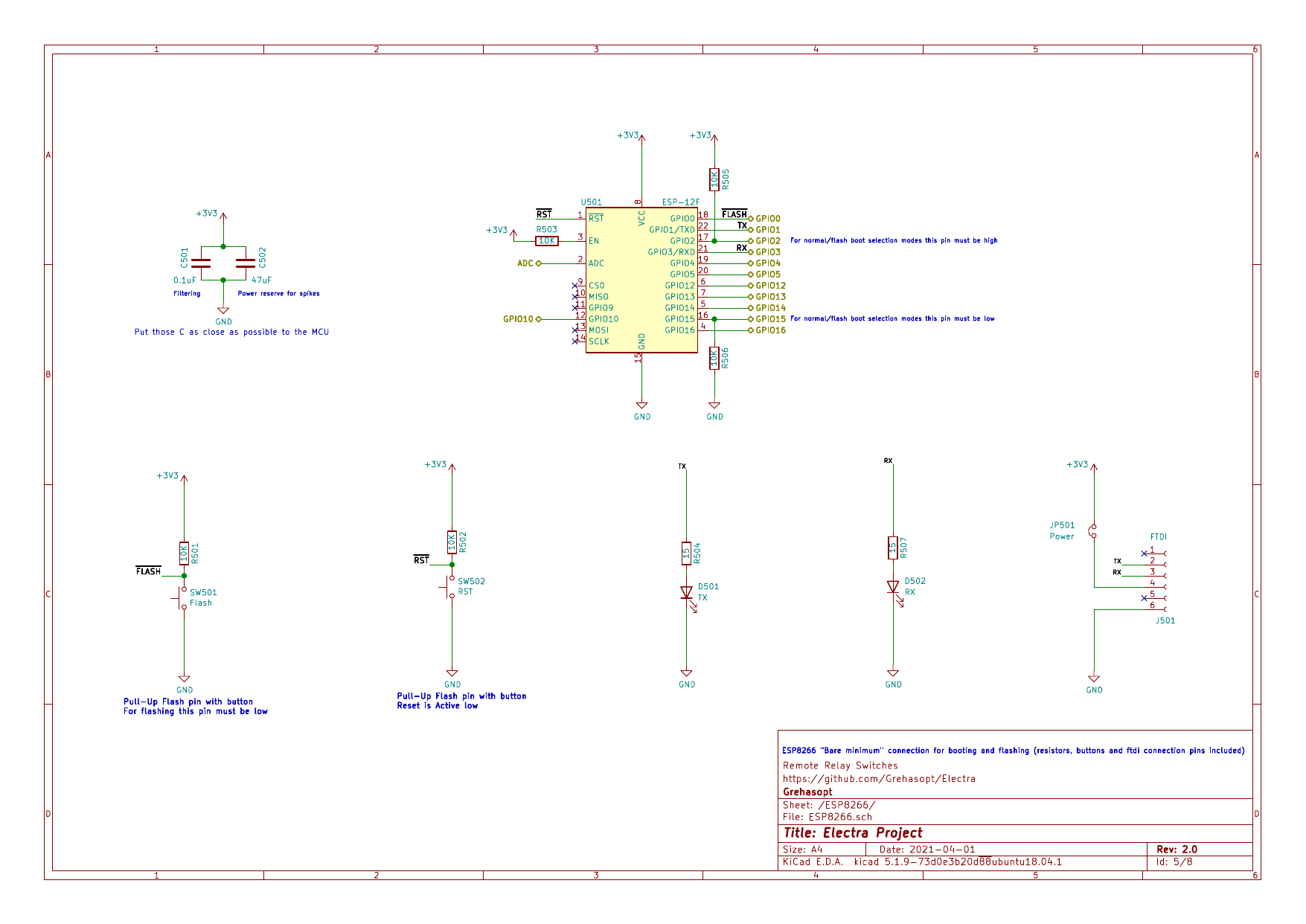
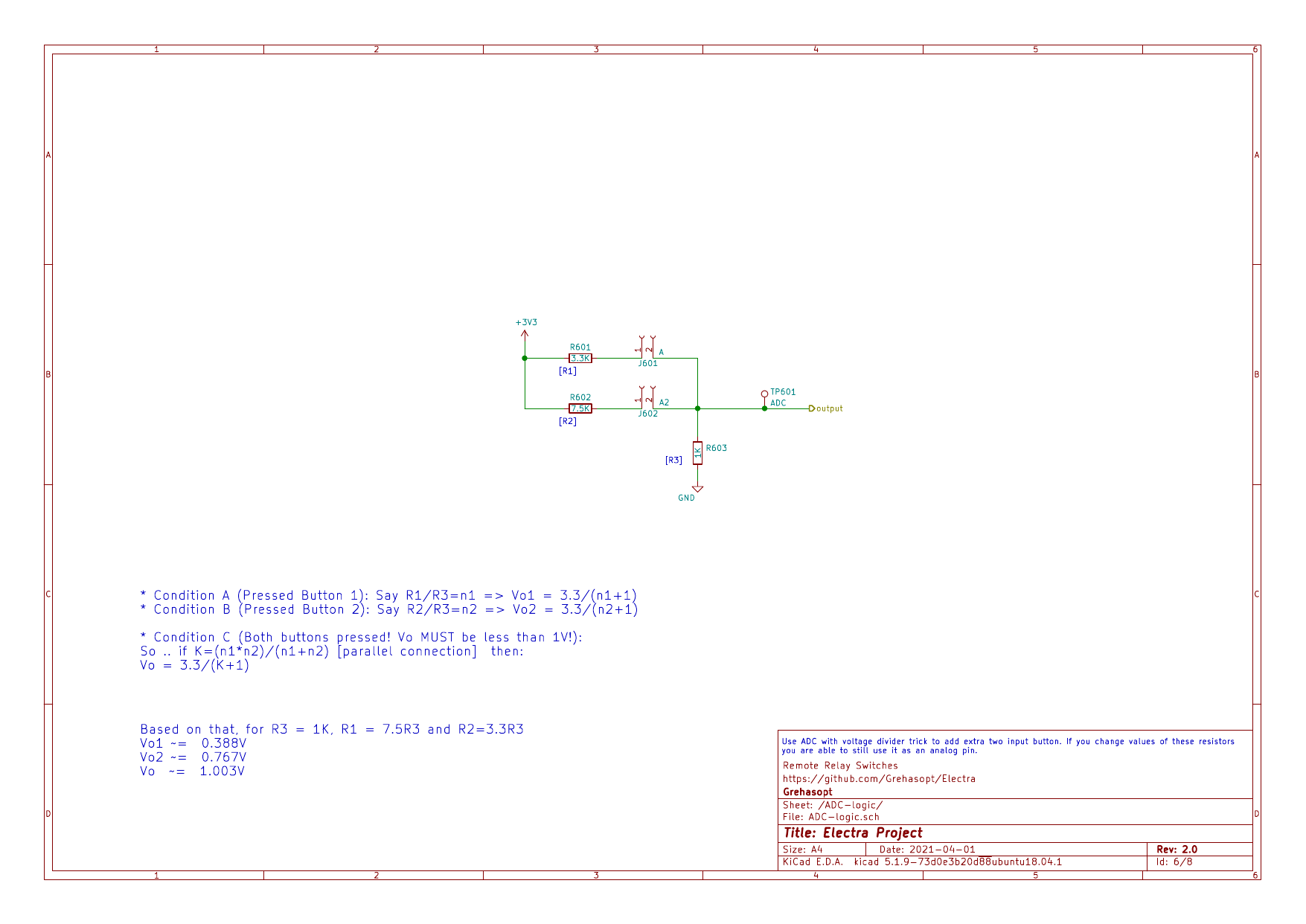
This project is licensed under the CERN-OHL-S-2.0 (applies from the very first commit on Mar 7, 2021) with the added condition that it may not be used for commercial purposes without prior permission from the license holder.
| Qty | Value | Footprint | References |
|---|---|---|---|
| 7 | 10K | Resistor_SMD:R_0603_1608Metric_Pad0.98x0.95mm_HandSolder | R401, R402, R501, R502, R503, R505, R506 |
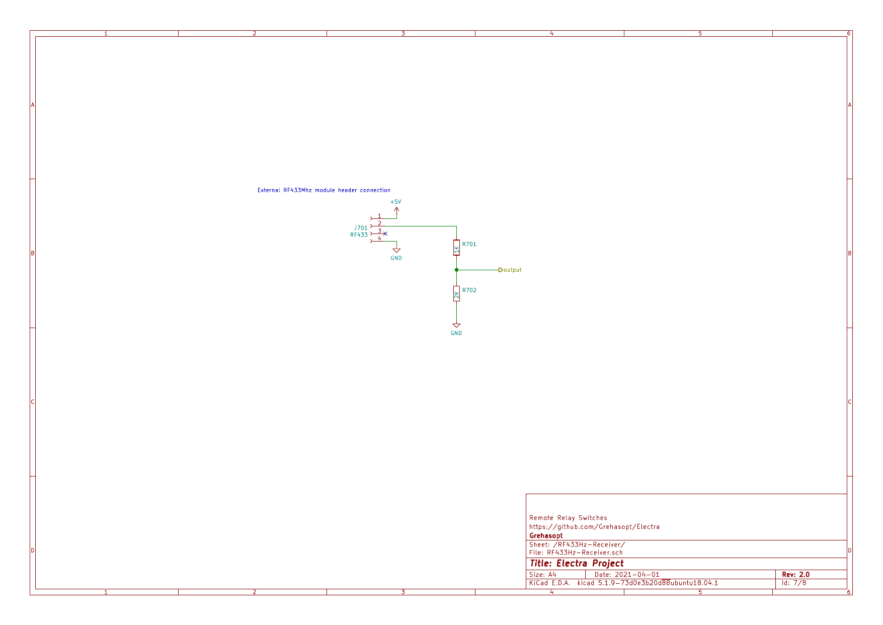
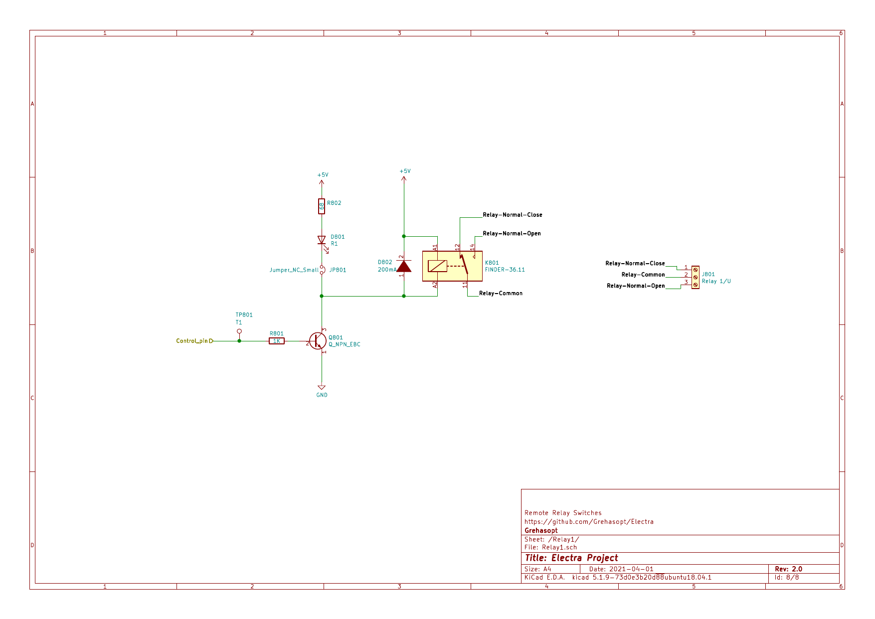
| 4 | 1K | Resistor_SMD:R_0603_1608Metric_Pad0.98x0.95mm_HandSolder | R301, R603, R701, R801 |
| 3 | 100uF | Capacitor_SMD:CP_Elec_6.3x5.4 | C201, C204, C205 |
| 3 | 1A | Diode_SMD:D_SMA_Handsoldering | D201, D202, D203 |
| 3 | Jumper_NC_Small | Jumper:SolderJumper-2_P1.3mm_Bridged_RoundedPad1.0x1.5mm | JP201, JP301, JP801 |
| 2 | 10uF | Capacitor_SMD:C_0805_2012Metric_Pad1.18x1.45mm_HandSolder | C202, C203 |
| 2 | 15 | Resistor_SMD:R_0805_2012Metric_Pad1.20x1.40mm_HandSolder | R504, R507 |
| 2 | 200mA | Diode_SMD:D_MiniMELF | D302, D802 |
| 2 | 68 | Resistor_SMD:R_0603_1608Metric_Pad0.98x0.95mm_HandSolder | R302, R802 |
| 2 | FINDER-36.11 | Relay_THT:Relay_SPDT_Finder_36.11 | K301, K801 |
| 2 | LOGO | Custom:Electricity-Causion-6.1mmX6.1mm-logo | G***, G*** |
| 2 | Q_NPN_EBC | Package_TO_SOT_SMD:SOT-323_SC-70 | Q301, Q801 |
| 1 | 0.1uF | Capacitor_SMD:C_0603_1608Metric_Pad1.08x0.95mm_HandSolder | C501 |
| 1 | 2K | Resistor_SMD:R_0603_1608Metric_Pad0.98x0.95mm_HandSolder | R702 |
| 1 | 3.3K | Resistor_SMD:R_0603_1608Metric_Pad0.98x0.95mm_HandSolder | R601 |
| 1 | 3V3 | TestPoint:TestPoint_Pad_D1.5mm | TP204 |
| 1 | 47uF | Capacitor_SMD:C_1206_3216Metric_Pad1.33x1.80mm_HandSolder | C502 |
| 1 | 5V | TestPoint:TestPoint_Pad_D1.5mm | TP203 |
| 1 | 7-12V | Connector_BarrelJack:BarrelJack_Horizontal | J202 |
| 1 | 7.5K | Resistor_SMD:R_0603_1608Metric_Pad0.98x0.95mm_HandSolder | R602 |
| 1 | 82 | Resistor_SMD:R_0603_1608Metric_Pad0.98x0.95mm_HandSolder | R201 |
| 1 | A | Connector_JST:JST_XH_B2B-XH-A_1x02_P2.50mm_Vertical | J601 |
| 1 | A2 | Connector_JST:JST_XH_B2B-XH-A_1x02_P2.50mm_Vertical | J602 |
| 1 | ADC | TestPoint:TestPoint_Pad_D1.5mm | TP601 |
| 1 | AMS1117-3.3 | Package_TO_SOT_SMD:SOT-223-3_TabPin2 | U202 |
| 1 | AMS1117-5.0 | Package_TO_SOT_SMD:SOT-223-3_TabPin2 | U201 |
| 1 | ESP-12F | RF_Module:ESP-12E | U501 |
| 1 | Extra1 | Connector_PinHeader_2.54mm:PinHeader_1x03_P2.54mm_Vertical | J101 |
| 1 | Extra2 | Connector_PinHeader_2.54mm:PinHeader_1x03_P2.54mm_Vertical | J103 |
| 1 | Flash | Button_Switch_SMD:SW_SPST_CK_RS282G05A3 | SW501 |
| 1 | GND | TestPoint:TestPoint_Pad_D1.5mm | TP201 |
| 1 | LOGO | Custom:dc-barrel-positive-polarity-5.1x5 | G*** |
| 1 | LOGO | Custom:Recycle-electronics-10mmx10mm-logo | G*** |
| 1 | PWR | LED_SMD:LED_0603_1608Metric_Pad1.05x0.95mm_HandSolder | D204 |
| 1 | R1 | LED_SMD:LED_0603_1608Metric_Pad1.05x0.95mm_HandSolder | D801 |
| 1 | R2 | LED_SMD:LED_0603_1608Metric_Pad1.05x0.95mm_HandSolder | D301 |
| 1 | RF433 | Connector_PinHeader_2.54mm:PinHeader_1x04_P2.54mm_Vertical | J701 |
| 1 | RST | Button_Switch_SMD:SW_SPST_CK_RS282G05A3 | SW502 |
| 1 | RTC | Connector_PinHeader_2.54mm:PinHeader_1x06_P2.54mm_Vertical | J102 |
| 1 | RX | LED_SMD:LED_0603_1608Metric_Pad1.05x0.95mm_HandSolder | D502 |
| 1 | Relay 1/U | TerminalBlock:TerminalBlock_bornier-3_P5.08mm | J801 |
| 1 | Relay 2/D | TerminalBlock:TerminalBlock_bornier-3_P5.08mm | J301 |
| 1 | S1/U | Connector_JST:JST_XH_B2B-XH-A_1x02_P2.50mm_Vertical | J401 |
| 1 | S2/D | Connector_JST:JST_XH_B2B-XH-A_1x02_P2.50mm_Vertical | J402 |
| 1 | T1 | TestPoint:TestPoint_Pad_D1.5mm | TP801 |
| 1 | T2 | TestPoint:TestPoint_Pad_D1.5mm | TP301 |
| 1 | TX | LED_SMD:LED_0603_1608Metric_Pad1.05x0.95mm_HandSolder | D501 |
| 1 | UART | Connector_PinHeader_2.54mm:PinHeader_1x04_P2.54mm_Vertical | J104 |
| 1 | USB | Connector_USB:USB_Micro-B_Molex-105017-0001 | J201 |
| 1 | Vin | TestPoint:TestPoint_Pad_D1.5mm | TP202 |
The 72 most common of 77 parts.
It measures 100 × 48.5 mm and has 2 copper layers, 1.6 mm thick.
77 parts, built around the ESP-12F, AMS1117-3.3 and AMS1117-5.0. The full list of its parts is on this page, with links to each part's symbol and footprint where PCBKit's library has them.
From the Grehasopt/Electra-pcb repository on GitHub, at the commit this page was made from: the board is pcb/Electra/Electra.kicad_pcb. PCBKit opens the board in the browser, with nothing to install.
Its repository publishes it under the CERN-OHL-S-2.0 licence: you may reuse it on that licence's terms (keep the author's notice, and for a copyleft licence share your changes alike).


klein0r/pcb-ws2812-wifi-controller
WiFi Controller for WS2812 LED Stripes


klein0r/pcb-ttl-ftdi-esp-adapter
PCB to connect a TTL reader either to an FTDI or ESP12-E/F (WiFi)


piwko28/smart-home-ebus-adapter
eBUS adapter PCB for use with ebusd-esp firmware as well as with other UART devices.

