
4 layers32 × 24 mm
SCH ESP32-P4 FUNCTION EV BOARD MIPI Camera Sub V1.1 20240529
OHNope/ESP32-P4X_MIPI_Camera_Sub_V1.1_KiCAD
The KiCAD project for ESP32-P4_FUNCTION_EV_BOARD_MIPI_Camera_Sub_V1.1_20240529
32 parts2

 grbbt/Camera-R20001
Open source repository for R2000 Camera development.
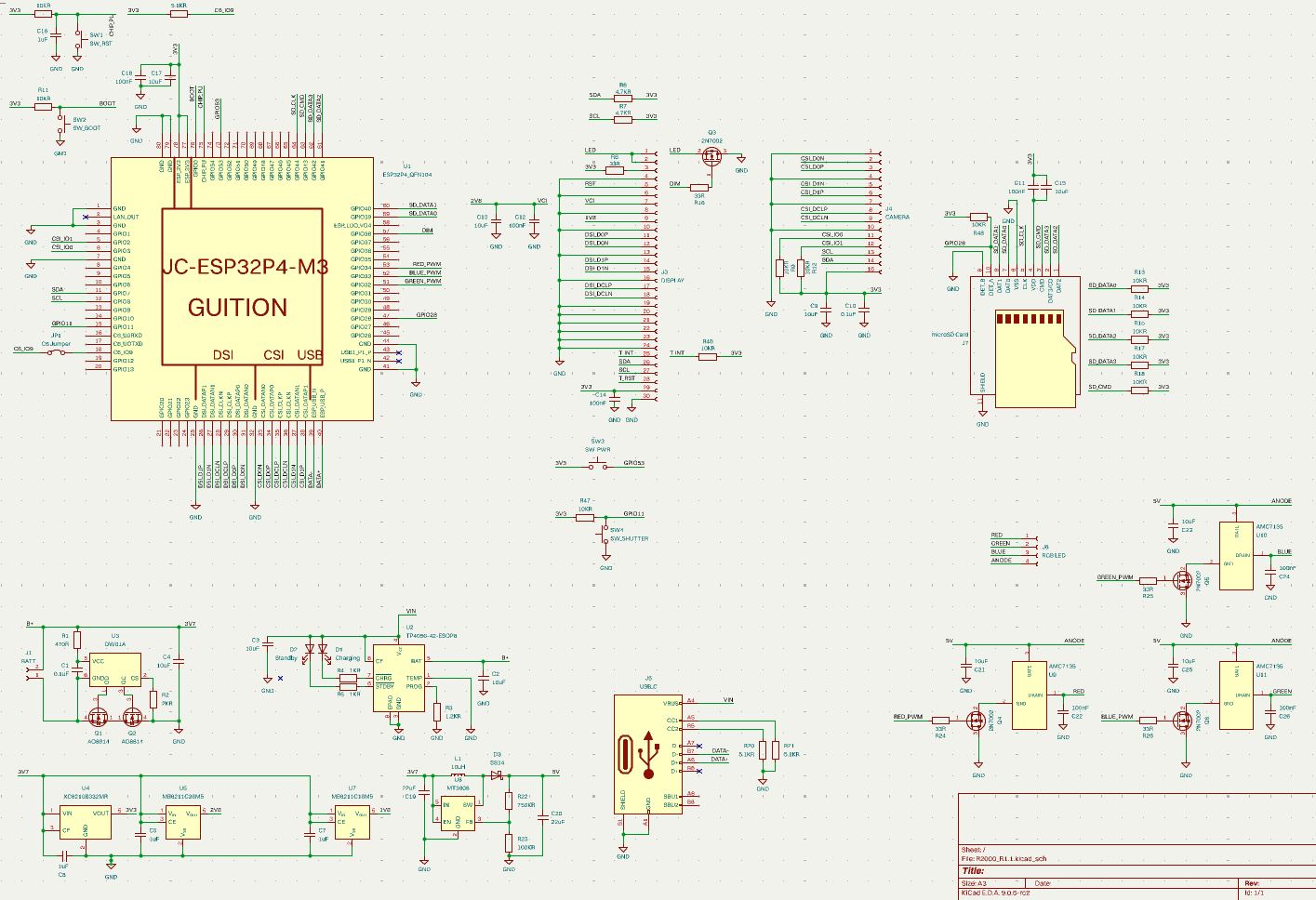
R2000 R1.1 is an open-source printed circuit board by grbbt, from the grbbt/Camera-R2000 repository on GitHub, published under the MIT licence. It is a 4-layer board with 85 parts on 117 nets, routed with 713 tracks and 196 vias.
It is built around the MT3608, DW01A and ME6211C18M5G-N, with the ME6211C28M5G-N, TP4056-42-ESOP8 and XC6210B332MR among its other parts. Its parts include 29 resistors, 25 capacitors, 9 ICs, 6 transistors and 6 connectors. It belongs with the ESP32 and RISC-V boards of this library.


A compact, round-bodied digital camera built around the ESP32-P4, designed for fun, accessible photography with a deliberate film-inspired aesthetic.


The R2000 is a hand-held digital camera on an 70mm circular PCB. Fixed-focus wide-angle lens, film-style filters, RGB flash, and a round touchscreen — all driven by an ESP32-P4 + ESP32-C6 SOM. It's a camera that prioritises feel and fun over clinical image quality.
Guition JC-ESP32P4-M3-C6 — a dual-chip SOM combining:
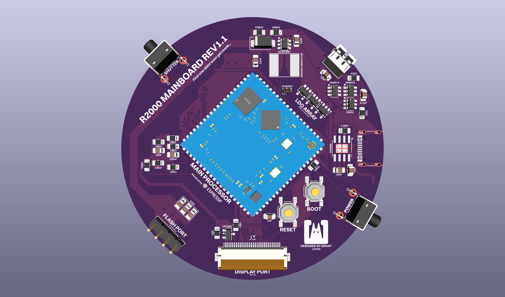
| Parameter | Value |
|---|---|
| Diameter | 70mm |
| Layers | 4 |
| Design tool | KiCad |
| Parameter | Value |
|---|---|
| Sensor | OV5640 |
| Interface | MIPI CSI-2 (2-lane) |
| Resolution | 5MP (2592×1944) |
| Focus | Fixed, wide angle |
| Hyperfocal | ~1.5m (everything from ~80cm to ∞ sharp) |
| Autofocus | None — VCM unused |
| Parameter | Value |
|---|---|
| Driver IC | ST7701S |
| Size | 2.1" round |
| Diameter | ~54mm |
| Interface | RGB parallel |
| Touch IC | GT911 (I2C) |
Three independent channels let you tune the colour temperature of each shot in software — or go full auto white-balance assist by sampling the scene before firing.
| Channel | Driver | Supply |
|---|---|---|
| Red 1W LED | AMC7135 (350mA CC) | 5V (MT3608 boost) |
| Green 1W LED | AMC7135 (350mA CC) | 5V (MT3608 boost) |
| Blue 1W LED | AMC7135 (350mA CC) | 5V (MT3608 boost) |
| Rail | Regulator | Supplies |
|---|---|---|
| 3.3V | XC6210B332 (1A) | SOM, display logic, SD, GT911 |
| 2.8V | ME6211C28 (600mA) | OV5640 AVDD |
| 1.8V | ME6211C18 (600mA) | OV5640 DOVDD |
| 1.5V | ME6211C15 (600mA) | OV5640 DVDD |
| 5V (flash) | MT3608 boost | RGB flash rail |
Battery: 1000mAh single-cell LiPo, ~503040 form factor, charged via TP5100.
| Layer | Component |
|---|---|
| RTOS | FreeRTOS (via ESP-IDF v5.3+) |
| Camera | esp_cam_sensor + esp_video (MIPI CSI DMA) |
| JPEG encode | esp_jpeg — hardware-accelerated on ESP32-P4 |
| Display | esp_lcd (ST7701S) + esp_lcd_touch (GT911) |
| UI | LVGL — hardware-accelerated via P4 PPA |
| Storage | esp_vfs_fat + sdmmc |
Core 0                         Core 1
├── Camera capture task        ├── LVGL UI task
├── JPEG encode task           └── Touch polling task
└── SD write task
Both cores run in genuine parallel — the live viewfinder never stutters during a write.
OV5640 sensor
  └── MIPI CSI-2 DMA → PSRAM framebuffer
        └── HW JPEG encoder
              └── SD write (FAT32)
└── JPEG filegit clone https://github.com/yourusername/R2000.git
cd R2000/firmware
idf.py set-target esp32p4
idf.py menuconfig # Set SD card GPIO, display config, etc.
idf.py build
idf.py -p /dev/ttyUSBx flash monitorhardware/pcb/hardware/bom/ — LCSC preferred for basic partsSee docs/gpio_map.md for the full 30-pin assignment covering RGB display, GT911 touch, OV5640 MIPI/I2C/XCLK, SD card, flash channels, and shutter button.
The R2000 isn't trying to be a precise instrument. No AF hunting, no deep menus, no lab-grade colour science. Wide angle and fixed focus means everything is sharp the moment you raise it. The filters are baked in, not bolted on. Round is unusual and that's the point.
If you want clinical accuracy, this is the wrong camera. If you want something that makes you actually want to take pictures, that's what this is for.
| Electrical | Status |
|---|---|
| PCB layout | ✅ First pass complete |
| Power system | ✅ LDO selection finalised |
| PCB Assembly & Testing | 🔧 In progress |
| Software | Status |
|---|---|
| Display / LVGL | 🔧 In progress |
| WiFi upload (C6) | 🔧 In progress |
| RGB flash driver | ⬜ Not started |
| Film filters | ⬜ Not started |
| SD storage | ⬜ Not started |
| Hardware | Status |
|---|---|
| Case Initial Design | 🔧 In progress |
| Case Prototyping | 🔧 In progress |
Hardware and firmware released under MIT License.
| Qty | Value | Footprint | References |
|---|---|---|---|
| 12 | 10KR | Resistor_SMD:R_0805_2012Metric_Pad1.20x1.40mm_HandSolder | R9, R10, R11, R12, R13, R14, R15, R17, R18, R46, R47, R48 |
| 10 | 10uF | Capacitor_SMD:C_0805_2012Metric_Pad1.18x1.45mm_HandSolder | C2, C3, C4, C9, C13, C15, C17, C21, C23, C25 |
| 7 | 100nF | Capacitor_SMD:C_0805_2012Metric_Pad1.18x1.45mm_HandSolder | C11, C12, C14, C18, C22, C24, C26 |
| 5 | 33R | Resistor_SMD:R_0805_2012Metric_Pad1.20x1.40mm_HandSolder | R6, R16, R24, R25, R26 |
| 4 | 1uF | Capacitor_SMD:C_0805_2012Metric_Pad1.18x1.45mm_HandSolder | C5, C7, C8, C16 |
| 4 | 2N7002 | Package_TO_SOT_SMD:SOT-23 | Q3, Q4, Q5, Q6 |
| 3 | 5.1KR | Resistor_SMD:R_0805_2012Metric_Pad1.20x1.40mm_HandSolder | R19, R20, R21 |
| 3 | AMC7135 | AMC7135:AMC7135_ASAP | U9, U10, U11 |
| 2 | 0.1uF | Capacitor_SMD:C_0805_2012Metric_Pad1.18x1.45mm_HandSolder | C1, C10 |
| 2 | 1KR | Resistor_SMD:R_0805_2012Metric_Pad1.20x1.40mm_HandSolder | R4, R5 |
| 2 | 22uF | Capacitor_SMD:C_0805_2012Metric_Pad1.18x1.45mm_HandSolder | C19, C20 |
| 2 | 4.7KR | Resistor_SMD:R_0805_2012Metric_Pad1.20x1.40mm_HandSolder | R7, R8 |
| 2 | AO8814 | Package_TO_SOT_SMD:TSOT-23-6 | Q1, Q2 |
| 1 | 1.2KR | Resistor_SMD:R_0805_2012Metric_Pad1.20x1.40mm_HandSolder | R3 |
| 1 | 100KR | Resistor_SMD:R_0805_2012Metric_Pad1.20x1.40mm_HandSolder | R23 |
| 1 | 10uH | Inductor_SMD:L_Taiyo-Yuden_NR-60xx_HandSoldering | BIGGGG INDUCTOR |
| 1 | 2KR | Resistor_SMD:R_0805_2012Metric_Pad1.20x1.40mm_HandSolder | R2 |
| 1 | 470R | Resistor_SMD:R_0805_2012Metric_Pad1.20x1.40mm_HandSolder | R1 |
| 1 | 750KR | Resistor_SMD:R_0805_2012Metric_Pad1.20x1.40mm_HandSolder | R22 |
| 1 | BATT | Connector_JST:JST_PH_B2B-PH-K_1x02_P2.00mm_Vertical | J1 |
| 1 | C6 Jumper | Connector_PinHeader_1.00mm:PinHeader_1x02_P1.00mm_Vertical | JP1 |
| 1 | CAMERA | Connector_FFC-FPC:TE_1-84952-5_1x15-1MP_P1.0mm_Horizontal | J4 |
| 1 | Charging | LED_SMD:LED_1206_3216Metric_Pad1.42x1.75mm_HandSolder | D1 |
| 1 | DISPLAY | Connector_FFC-FPC:Hirose_FH12-30S-0.5SH_1x30-1MP_P0.50mm_Horizontal | J3 |
| 1 | DW01A | Package_TO_SOT_SMD:SOT-23-6 | U3 |
| 1 | ESP32P4_QFN104 | Guition ESP32:JC-ESP32P4-M3_V0.2 | U1 |
| 1 | ME6211C18M5 | Package_TO_SOT_SMD:SOT-23-5 | U7 |
| 1 | ME6211C28M5 | Package_TO_SOT_SMD:SOT-23-5 | U5 |
| 1 | MT3608 | Package_TO_SOT_SMD:SOT-23-6 | 5V BOOST |
| 1 | RGB LED | Connector_PinHeader_2.54mm:PinHeader_1x04_P2.54mm_Vertical | J6 |
| 1 | SS34 | Diode_SMD:D_SMA | D3 |
| 1 | SW_BOOT | Button_Switch_SMD:SW_SPST_TL3342 | SW2 |
| 1 | SW_PWR | Button_Switch_THT:SW_Tactile_SPST_Angled_PTS645Vx58-2LFS | POWER |
| 1 | SW_RST | Button_Switch_SMD:SW_SPST_TL3342 | SW1 |
| 1 | SW_SHUTTER | Button_Switch_THT:SW_Tactile_SPST_Angled_PTS645Vx58-2LFS | SHUTTER |
| 1 | Standby | LED_SMD:LED_1206_3216Metric_Pad1.42x1.75mm_HandSolder | D2 |
| 1 | TP4056-42-ESOP8 | Package_SO:SOIC-8-1EP_3.9x4.9mm_P1.27mm_EP2.41x3.3mm_ThermalVias | U2 |
| 1 | USB_C | Connector_USB:USB_C_Receptacle_G-Switch_GT-USB-7010ASV | J5 |
| 1 | XC6210B332MR | Package_TO_SOT_SMD:SOT-23-5 | U4 |
| 1 | microSD Card | Connector_Card:microSD_HC_Hirose_DM3AT-SF-PEJM5 | J7 |
85 parts, built around the MT3608, DW01A, ME6211C18M5G-N and ME6211C28M5G-N. The full list of its parts is on this page, with links to each part's symbol and footprint where PCBKit's library has them.
From the grbbt/Camera-R2000 repository on GitHub, at the commit this page was made from: the board is pcb/R2000_R1.1.kicad_pcb and its schematic pcb/R2000_R1.1.kicad_sch. PCBKit opens the board in the browser, with nothing to install.
Its repository publishes it under the MIT licence: you may reuse it on that licence's terms (keep the author's notice, and for a copyleft licence share your changes alike).
OHNope/ESP32-P4X_MIPI_Camera_Sub_V1.1_KiCAD
The KiCAD project for ESP32-P4_FUNCTION_EV_BOARD_MIPI_Camera_Sub_V1.1_20240529

OHNope/sc035hgs-esp32-p4x-camera-adapter-mod
本仓库在 ESP32-P4XMIPICameraSubV1.1KiCAD(Espressif 官方相机转接板的 KiCad 转换版)基础上,修改为 SC035HGS 相机模组用的转接板。基础工程(导入修复、检查结果)的说明见它的 README。


MAATHES-THILAK-K/ESP32-S3_FLIGHT_CONTROLLER
A custom-designed flight controller based on the ESP32-S3 module, built for compatibility with the esp-fc firmware and Betaflight-like configuration.

nikolaus018/dji-fcc-esp32
ESP32-S3 firmware that switches a DJI N1 remote to FCC mode over USB (replaces the Android app)

devKOff/pcb-lipo-power-management-system
An integrated PCB power management system for single-cell Li-Po batteries featuring onboard charging, circuit protection, and a DC-DC boost converter with selectable 5V and 12V DC outputs.

