4 layers210.6 × 220 mm
CMAIN PCB
Arrow-air/project-caribou
Project Caribou documentation, designs, and project artifacts.
248 parts177CERN-OHL-S-2.0

 gpgreen/avdisplay-cape
Kicad hardware design for Beaglebone cape intended for Avionics project. Dual CAN interface and power.
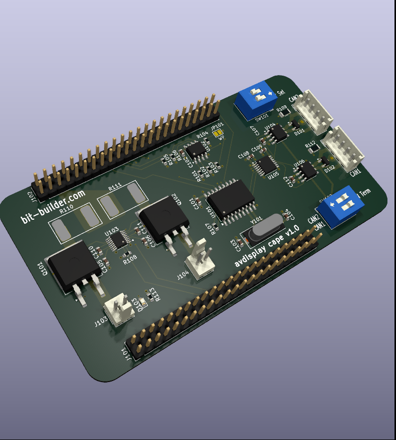
Avdisplay cape is an open-source printed circuit board by gpgreen, from the gpgreen/avdisplay-cape repository on GitHub. It is a 4-layer board of 100 × 55 mm with 46 parts on 126 nets, routed with 352 tracks and 56 vias.
It is built around the MCP2551-I/SN-HG, CAT24C256LI and TXB0104PW, with the CDSOT23-T24CAN and PSMN4R3-30BL,118-VB among its other parts. Its parts include 13 resistors, 12 capacitors, 6 ICs, 6 connectors and 3 diodes. It belongs with the interfaces and adapters boards of this library.


Kicad design for beaglebone black cape. Provides Dual CAN bus & bus protection. Provides 4A of 5V power to the beaglebone black using dual offboard 1.5A switching power supplies. These are load balanced using a LTC4370 device. Since the project is also using a LCD display, only one of the beaglebone's dual CAN devices is available due to pin conflicts, so another external MCP2515 CAN controller connected via SPI is onboard.
The design is intended to use two Sparkfun buck boost power supplies which use a TPS63070 device. The input range is 3-16V. The project is supplied from a 12V system. The output on the breakout boards is selected to 5V and each device connected to the board with the provided JST connectors. With a heatsink installed on each device, they are capable of providing 2A for a total of 4A. The 12V input should have diode protection and a fuse as those are not installed on either the buck-boost breakout boards or the cape.
| Qty | Value | Footprint | References |
|---|---|---|---|
| 7 | 0.1 uF | Capacitor_SMD:C_0603_1608Metric | C101, C102, C105, C107, C108, C109, C112 |
| 6 | 5.6K | Resistor_SMD:R_0603_1608Metric | R101, R102, R103, R104, R105, R106 |
| 2 | 120 | Resistor_SMD:R_1206_3216Metric | R109, R112 |
| 2 | 2.5m | My Custom Footprints:WSLP3921 | R110, R111 |
| 2 | 30pF | Capacitor_SMD:C_0603_1608Metric | C103, C104 |
| 2 | 39nF | Capacitor_SMD:C_0603_1608Metric | C110, C111 |
| 2 | CDSOT23-T24CAN | Package_TO_SOT_SMD:SOT-23 | D101, D102 |
| 2 | MCP2551-I-SN | Package_SO:SOIC-8_3.9x4.9mm_P1.27mm | U104, U106 |
| 2 | PSMN4R3-30BL,118 | Package_TO_SOT_SMD:TO-263-2 | Q101, Q102 |
| 1 | 0.18uF | Capacitor_SMD:C_0603_1608Metric | C106 |
| 1 | 10K | Resistor_SMD:R_0603_1608Metric | R107 |
| 1 | 16 MHz | Crystal:Crystal_SMD_HC49-SD | Y101 |
| 1 | 30.1K | Resistor_SMD:R_0603_1608Metric | R108 |
| 1 | 680 | Resistor_SMD:R_0603_1608Metric | R113 |
| 1 | Address Selector | Button_Switch_THT:SW_DIP_SPSTx02_Slide_9.78x7.26mm_W7.62mm_P2.54mm | SW101 |
| 1 | CAN Term | Button_Switch_THT:SW_DIP_SPSTx02_Slide_9.78x7.26mm_W7.62mm_P2.54mm | SW102 |
| 1 | CAN1 | Connector_JST:JST_EH_B4B-EH-A_1x04_P2.50mm_Vertical | J106 |
| 1 | CAN2 | Connector_JST:JST_EH_B4B-EH-A_1x04_P2.50mm_Vertical | J105 |
| 1 | CAT24C256 | Package_SO:SOIC-8_3.9x4.9mm_P1.27mm | U102 |
| 1 | LED | LED_SMD:LED_0603_1608Metric | D103 |
| 1 | LTC4370xMS | Package_SO:MSOP-16_3x4mm_P0.5mm | U103 |
| 1 | MCP2515-xSO | Package_SO:SOIC-18W_7.5x11.6mm_P1.27mm | U101 |
| 1 | P8 | Connector_PinHeader_2.54mm:PinHeader_2x23_P2.54mm_Vertical | J101 |
| 1 | P9 | Connector_PinHeader_2.54mm:PinHeader_2x23_P2.54mm_Vertical | J102 |
| 1 | SolderJumper_2_Open | Jumper:SolderJumper-2_P1.3mm_Open_Pad1.0x1.5mm | JP101 |
| 1 | TXB0104PW | Package_SO:TSSOP-14_4.4x5mm_P0.65mm | U105 |
| 1 | VIN1 | Connector_Molex:Molex_KK-254_AE-6410-02A_1x02_P2.54mm_Vertical | J103 |
| 1 | VIN2 | Connector_Molex:Molex_KK-254_AE-6410-02A_1x02_P2.54mm_Vertical | J104 |
It measures 100 × 55 mm and has 4 copper layers, 1.6 mm thick.
46 parts, built around the MCP2551-I/SN-HG, CAT24C256LI, TXB0104PW and CDSOT23-T24CAN. The full list of its parts is on this page, with links to each part's symbol and footprint where PCBKit's library has them.
From the gpgreen/avdisplay-cape repository on GitHub, at the commit this page was made from: the board is avdisplay-cape.kicad_pcb and its schematic avdisplay-cape.kicad_sch. PCBKit opens the board in the browser, with nothing to install.
Its repository states no licence, so its author keeps all rights: ask gpgreen before reusing the design.
Arrow-air/project-caribou
Project Caribou documentation, designs, and project artifacts.


Robast-GmbH/PCB_Designs
This repository contains all the necessary files and instructions for the PCBs that are designed using KiCad. Here is an overview of the main components: - .github: Contains Github-specific configurations, including…


lhr-solar/Power-Generation-Curve-Tracer
The current maintainer of this project is Matthew Yu as of 05/20/2023. His email is matthewjkyu@gmail.com.

corbosiny/SolarCar
All code relating to solar car like: BPS, telemetry, web dev, and more.

lhr-solar/PS-BPSLeader
Reads voltage, temperature, and current of the main battery pack from the Segment Monitoring Board and HV Carrier boards to ensure the battery remains in a safe state.

dimembermatt/MPPT-Design
Design and documentation of a custom MPPT for LHR Solar. Created in part with Professor Alex Hanson's ECE 394J Power Electronics Class.