4 layers100 × 55 mm
Avdisplay cape
gpgreen/avdisplay-cape
Kicad hardware design for Beaglebone cape intended for Avionics project. Dual CAN interface and power.
46 parts

 gpgreen/can-bridge-hardware
Kicad project for can-usb bridge
Can bridge is an open-source printed circuit board by gpgreen, from the gpgreen/can-bridge-hardware repository on GitHub. It is a 2-layer board of 59.5 × 54 mm with 14 parts on 53 nets, routed with 62 tracks and 5 vias.
It is built around the MCP2551-I/SN-HG, TXB0104PW and 78RB02ST. Its parts include 3 capacitors, 3 resistors, 2 ICs, 2 diodes and 2 switches. It belongs with the interfaces and adapters and microcontroller boards boards and the AVR (ATmega, ATtiny) boards of this library.


Kicad design for a CAN to USB serial bridge. Based on a Nucleo-F103RB development board with an arduino shield that provides the CAN transceiver for the CAN controller that resides on the STM32F103RB device on the dev board.
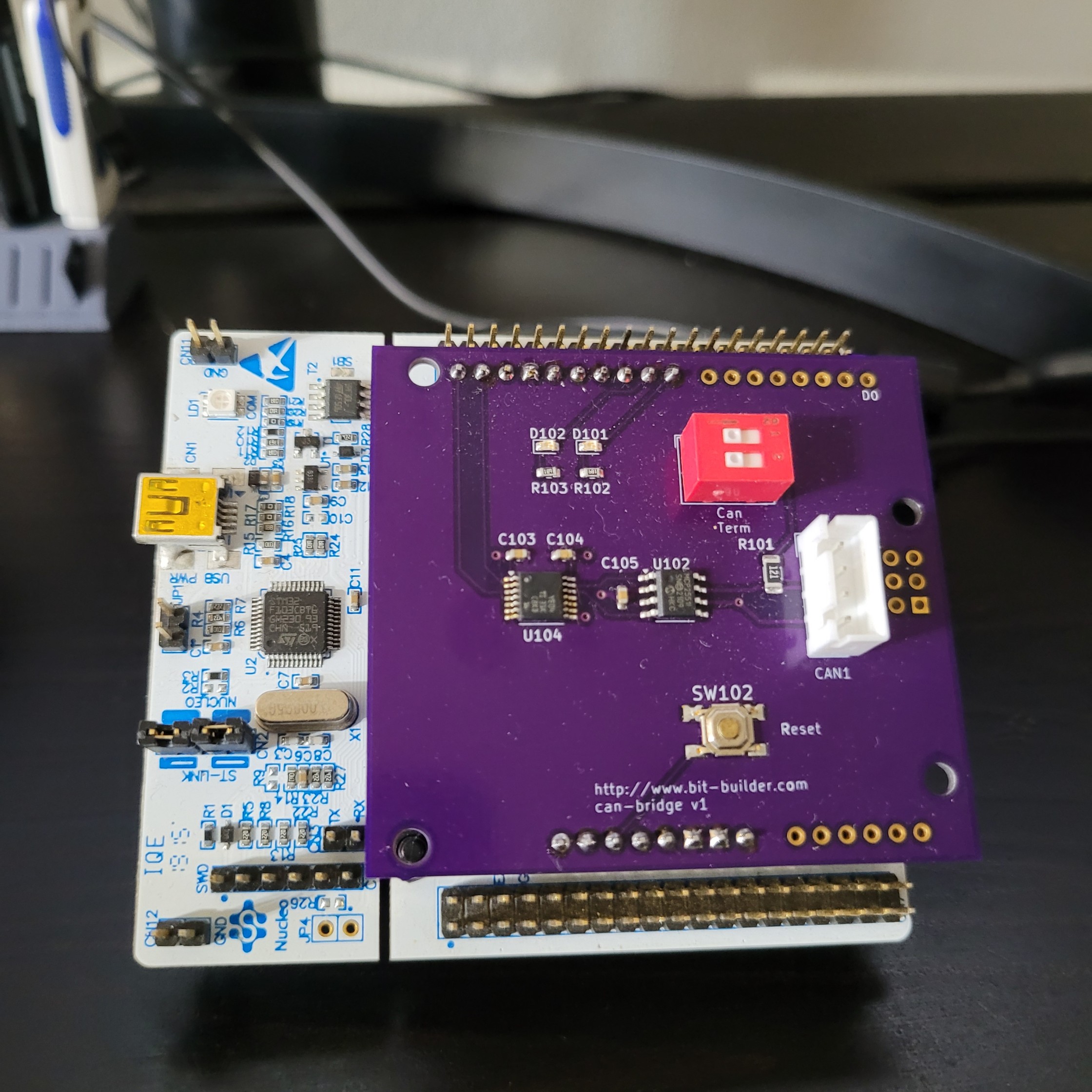
The CAN controller on the Nucleo dev board, is routed to a MCP2551 transceiver on the arduino daughter board. The two CAN outputs from the transceiver go to the CAN1 connector on the daughter board. This connector is pinned:
 +---+
 | o | NC
[| o | CANH
[| o | CANL
 | o | NC
 +---+
  CAN1
A 120 ohm terminating resistor is also on the board. To use this resistor, set the DIP switch position 1 to on.
The firmware is designed to be used with Serial CAN from the canutils project. Rust-based project.
| Qty | Value | Footprint | References |
|---|---|---|---|
| 3 | 0.01nF | Capacitor_SMD:C_0603_1608Metric | C103, C104, C105 |
| 2 | 200 | Resistor_SMD:R_0603_1608Metric | R102, R103 |
| 2 | LED | LED_SMD:LED_0603_1608Metric | D101, D102 |
| 1 | 120 | Resistor_SMD:R_1206_3216Metric | R101 |
| 1 | 78RB02ST | Button_Switch_THT:SW_DIP_SPSTx02_Slide_9.78x7.26mm_W7.62mm_P2.54mm | SW101 |
| 1 | Arduino_Uno_R3_Shield | PCM_arduino-library:Arduino_Uno_R3_Shield | A101 |
| 1 | CAN1 | Connector_JST:JST_EH_B4B-EH-A_1x04_P2.50mm_Vertical | J102 |
| 1 | MCP2551-I-SN | Package_SO:SOIC-8_3.9x4.9mm_P1.27mm | U102 |
| 1 | Reset | My Custom Footprints:OnShine KPT-1187B | SW102 |
| 1 | TXB0104PW | Package_SO:TSSOP-14_4.4x5mm_P0.65mm | U104 |
It measures 59.5 × 54 mm and has 2 copper layers, 1.6 mm thick.
14 parts, built around the MCP2551-I/SN-HG, TXB0104PW and 78RB02ST. The full list of its parts is on this page, with links to each part's symbol and footprint where PCBKit's library has them.
From the gpgreen/can-bridge-hardware repository on GitHub, at the commit this page was made from: the board is can-bridge.kicad_pcb and its schematic can-bridge.kicad_sch. PCBKit opens the board in the browser, with nothing to install.
Its repository states no licence, so its author keeps all rights: ask gpgreen before reusing the design.
gpgreen/avdisplay-cape
Kicad hardware design for Beaglebone cape intended for Avionics project. Dual CAN interface and power.

Robast-GmbH/PCB_Designs
This repository contains all the necessary files and instructions for the PCBs that are designed using KiCad. Here is an overview of the main components: - .github: Contains Github-specific configurations, including…


menloresearch/asimov-1
v1 of Asimov, an open-source humanoid robot

andykarpov/karabas-pro
FPGA based retrocomputer with FDD and HDD controllers


