2 layers119.4 × 116.8 mm
Teletext In Vision Decoder
avrovulcanxh607/teletext-decoder
This repo is an attempt to open-source my teletext decoder.
79 parts4

 goscickiw/Analog-Video-Comb-Filter9
Analog Composite Video to S-Video comb filter board using SAA4960, SAA4961 or SAA4963 integrated circuit
Analog Video Comb Filter is an open-source printed circuit board by goscickiw, from the goscickiw/Analog-Video-Comb-Filter repository on GitHub, published under the CC-BY-SA-4.0 licence. It is a 2-layer board of 51.5 × 104.1 mm with 82 parts on 72 nets, routed with 278 tracks and 7 vias.
It is built around the LM1881, 74HC04D and L7805, with the BC548 among its other parts. Its parts include 32 capacitors, 21 resistors, 7 ICs, 6 inductors and 4 connectors.


Analog Composite Video to S-Video comb filter board using SAA4960, SAA4961 or SAA4963 integrated circuit.
This project uses end-of-life components that are no longer manufactured. If you want to build this, make sure that you can obtain all components before starting. Used or new-old-stock parts can sometimes be found online.
This is a fully analog alternative to digital comb filters such as Extron YCS Transcoder or YCS 100. That doesn't mean it will give better results though. I just made it because I didn't find any fully analog device like that on the market and I wanted one.
The comb filter is used to convert a composite video signal into an S-Video (Y/C) signal. Comb filters are much better than passive LC filters usually built into composite video displays, as they can preserve the frequencies of luminance that overlap with chrominance, providing higher image detail while removing dot crawl, and remove those overlapping luminance frequencies from the chrominance signal which reduces color artifacts.
When using the SAA4960 integrated circuit, PAL B, D, G, H and I systems are supported.
SAA4961 provides aditional support for PAL M, N and NTSC M systems.
When using the SAA4963 integrated circuit, only the NTSC M system is supported.
The board is designed to fit inside a KRADEX Z-76 enclosure.
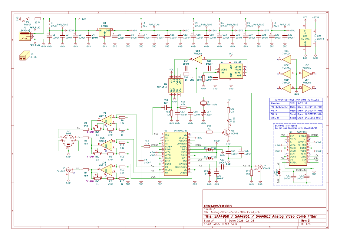
A composite video signal is fed in through an RCA connector (J4). The signal is terminated with a 75 ohm resistor and fed to U3 (or U7), U4 and U6 through 100 nF capacitors.
The LM1881 sync separator (U6) uses the composite video signal to generate a burst gate signal. The burst gate signal passes through a 74HC04 inverter (U5) to the MC44144 subcarrier PLL (U4).
U4 uses the composite video signal and the burst gate signal to generate a subcarrier frequency synchronized to the colorburst of the composite video signal. This subcarrier signal is then passed to the FSC input of U3/U7.
The SAA4960/61/63 comb filter (U3 or U7) is fed with the composite video signal and the synchronized subcarrier signal. The jumpers SYS1 and SYS2 set the video standard, and the jumper LPF can be used to disable the input low-pass filter. This circuit outputs filtered luminance and chrominance signals and a delayed composite video passthrough signal (when using SAA4963, the CVBYP jumper has to be shorted to allow non-delayed composite video passthrough). Those signals are then fed to the output amplifiers.
The AD813 triple op-amp (U2) is used for the output amplifiers. The output signals from the SAA4960/611 are DC-biased by around 1V, so a non-rail-to-rail op-amp like the AD813 is viable. The gain can be adjusted from approx. 1,5x to 2,5x with RV1, RV2 and RV3.
| Assembled rev.2 devices (PAL and NTSC) | Completed, operating device in enclosure |
|---|---|
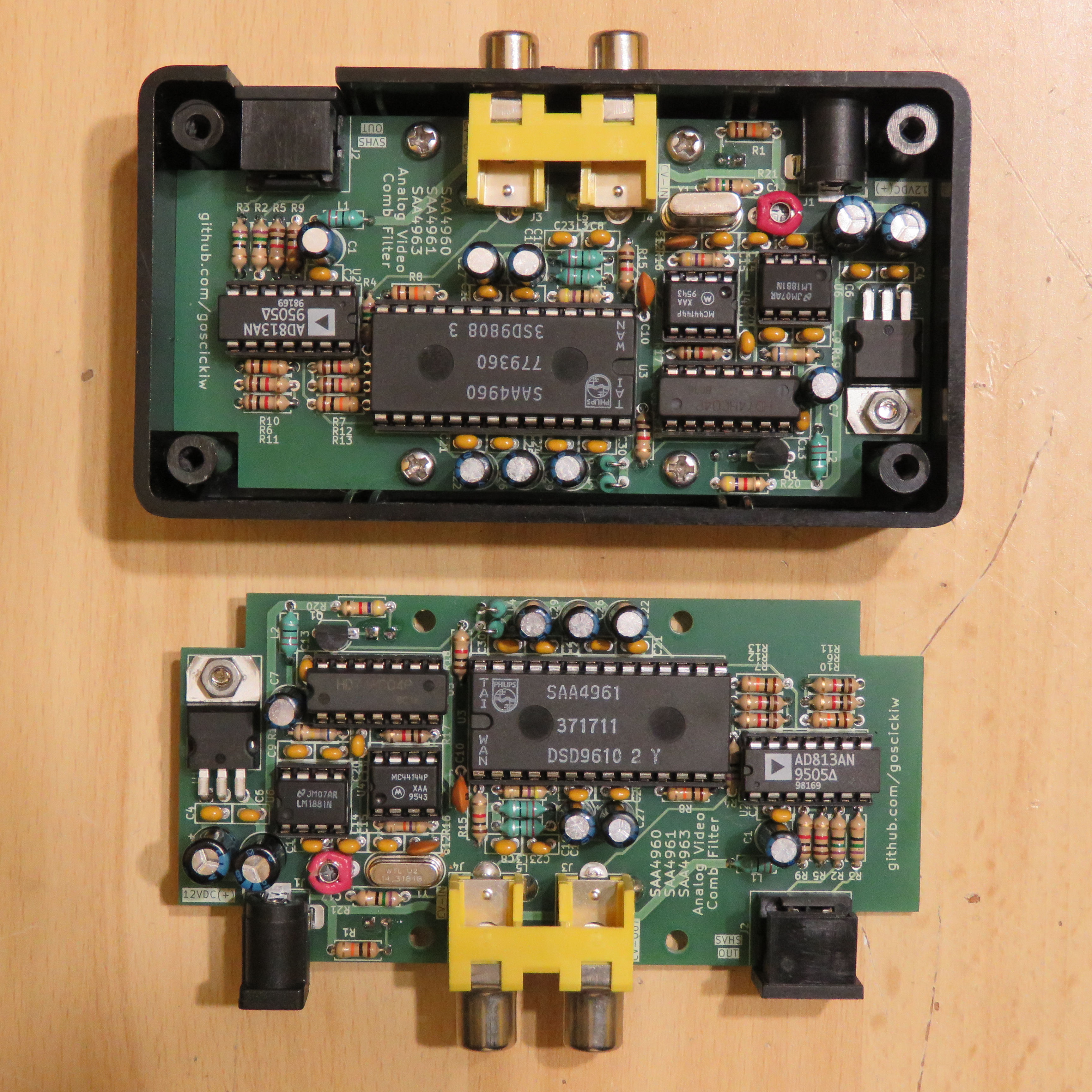 | 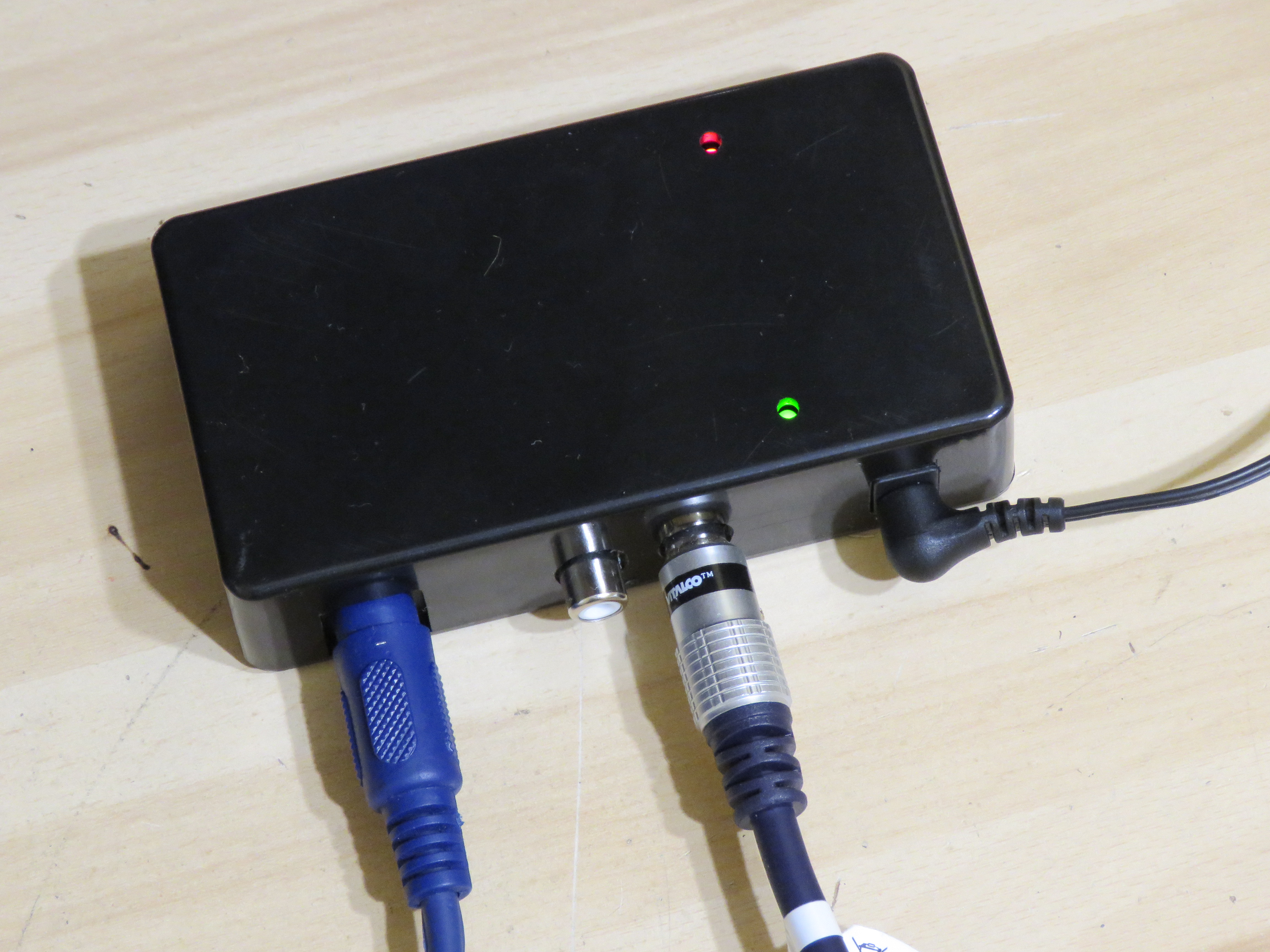 |
| No filter | LC filter |
|---|---|
| Luminance detail is preserved, but dot crawl is visible across the entire picture. | Dot crawl is mostly removed, but luminance loses some sharpness, and higher frequency luminance components (responsible for sharpness) are left in chrominance causing color artifacts. |
 | 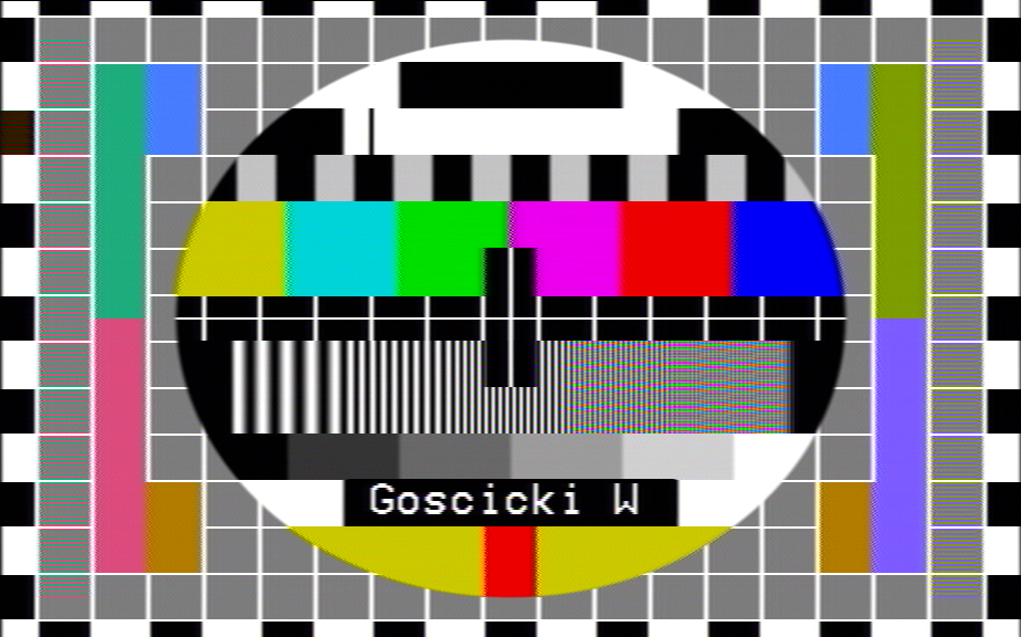 |
| This analog comb filter | MC141627 digital comb filter (for comparison, Extron YCS transcoder) |
| Dot crawl is mostly removed and luminance sharpness is mostly preserved. Higher frequency luminance components are properly separated from chrominance. | More effective than the analog comb filter. |
 |  |
| No filter | LC filter |
|---|---|
| Luminance detail is preserved, but dot crawl is visible in colored sections. | Dot crawl is mostly removed, but luminance loses some sharpness. |
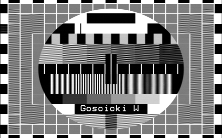 | 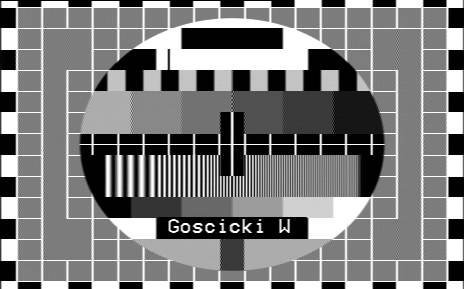 |
| This analog comb filter | MC141627 digital comb filter (for comparison, Extron YCS transcoder) |
| Dot crawl is mostly removed and luminance sharpness is mostly preserved. | More effective than the analog comb filter. |
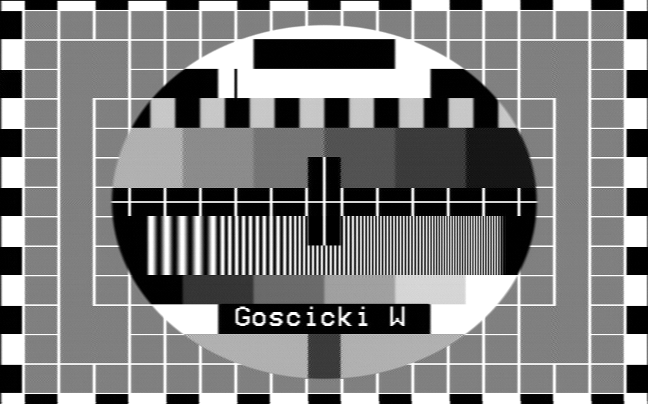 | 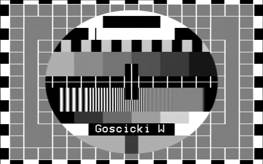 |
D1 shows that the device is receiving power.
D2 shows that the comb filter is operating (U3 is in COMB mode). I'm not sure if U3 will ever not be in COMB mode when used in this circuit, so this LED might be unnecessary. SAA4963 does not have the output needed by this LED, so if it is used, then R19, R20, D2 and Q1 can be left unpopulated.
When using SAA4960 or SAA4961, install C24 and C26, and leave C31 and C32 unpopulated.
When using SAA4963, install C31 and C32, and leave C24 and C26 unpopulated.
SAA4961 only. When using SAA4960, SYS1 and SYS2 jumpers should be left open. When using SAA4963, the jumpers are not connected.
Appropriate crystal for the subcarrier oscillator should be installed depending on the jumper setting. If the standard is going to be changed frequently, it may be possible to install a socket for the crystal, however it should be taken into account that MC44144 is sensitive to additional capacitance at the crystal.
| Standard | SYS1 | SYS2 | Crystal required |
|---|---|---|---|
| PAL B/D/G/H/I | Open | Open | 17,734475 MHz |
| PAL M | Open | Short | 14,302444 MHz |
| PAL N | Short | Open | 14,328225 MHz |
| NTSC M | Short | Short | 14,31818 MHz |
The SAA4960, SAA4961 and SAA4963 integrated circuits have a built-in low-pass filter on the composite video input. With SAA4960 and SAA4961, this filter can be disabled by shorting the LPF jumper, but it's recommended to leave it on. With SAA4963, the jumper is not connected and the filter is always on.
| LPF | Filter mode |
|---|---|
| Open | Filter enabled |
| Short | Filter disabled |
SAA4963 doesn't have a composite video output, so the CVBYP jumper was provided for composite video passthrough. When the jumper is shorted, the video signal for composite video output is taken from pin 13 (composite video input) of SAA4963. The DC bias for the output amplifier is provided by the clamping circuit inside SAA4963. Do not install R12 to avoid additional load to the clamping circuit. This configuration has not been tested and may not work correctly. Leave the jumper open if shorting it causes issues for the comb filter.
WARNING: This jumper must never be shorted if using SAA4960/61.
| CVBYP | Usage |
|---|---|
| Open | When using SAA4960 or SAA4961. |
| Short | When using SAA4963. |
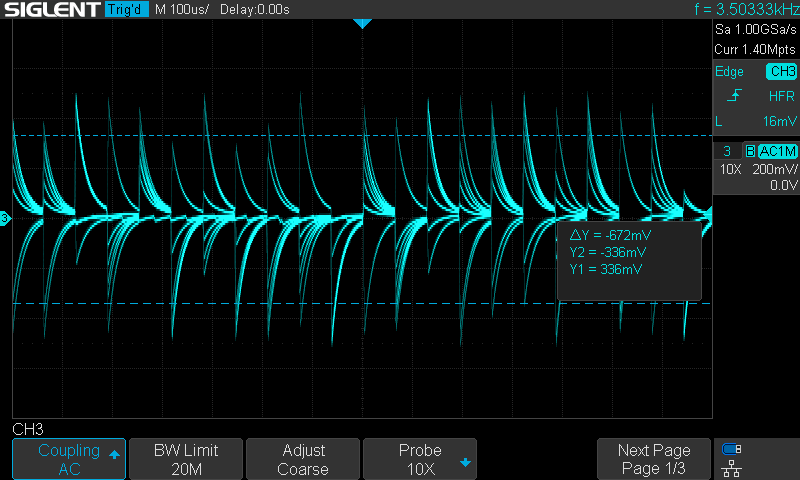
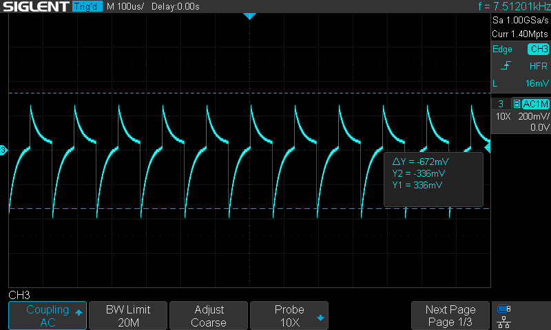
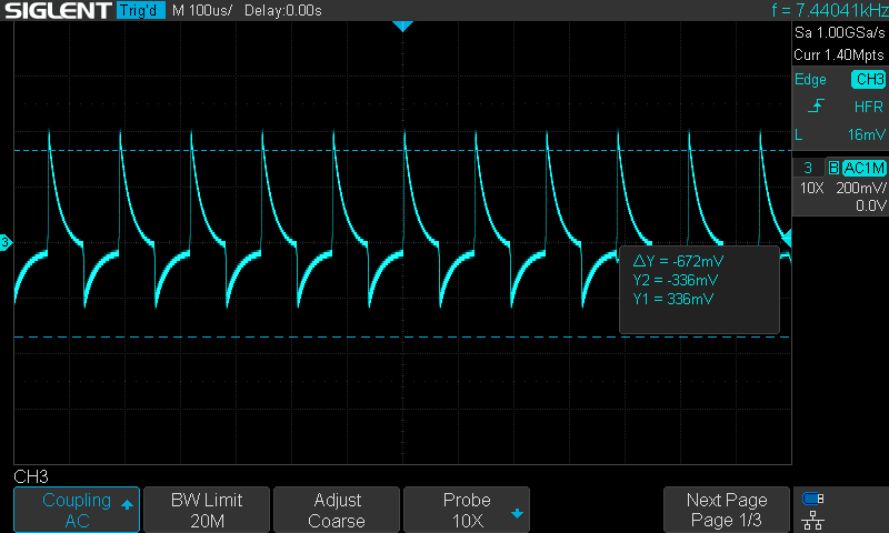
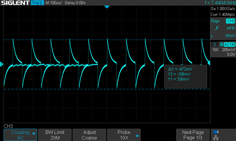
After assembly, including setting the jumpers and installing the correct crystal depending on the analog video standard, the variable capacitor C17 will have to be adjusted so that the PLL locks correctly to the color subcarrier and the loop control voltage is centered.
Use the following procedure for adjustment:
| Not locked | Locked, not adjusted | Best adjustment |
|---|---|---|
 |   |  |
| Not locked | Locked, not adjusted | Best adjustment |
|---|---|---|
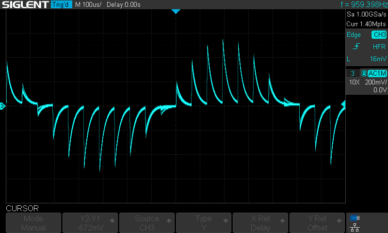 | 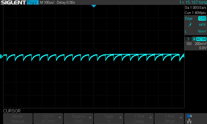 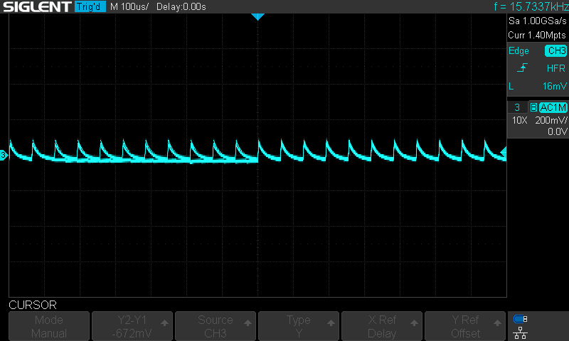 | 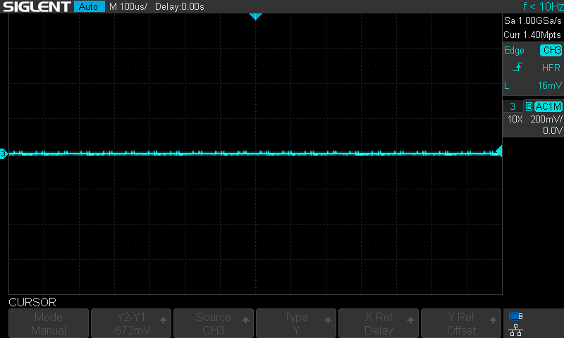 |
flowchart LR
A{Able to obtain waveform shown in <b>Best adjustment</b> by adjusting C17?} -- Yes --> B([PLL correctly adjusted.]);
A -->|No| C{"PLL able to lock (one of <b>Locked, not adjusted</b> waveforms)?"};
C -->|Yes| D{Does waveform resemble the <b>top</b> or <b>bottom</B> picture in <b>Locked, not adjusted</b>?};
C -->|No| E["Measure frequency at U4 pin 1 (FSC output), and adjust C17 to get as close as possible to required frequency."];
E --> F{Is the frequency higher or lower than required?};
F -->|Higher| G[replace C17 with a higher max. value trim capacitor, or add a parallel capacitor.];
F -->|Lower| H[replace C17 with a lower min. value trim capacitor.];
D -->|Top| G;
D -->|Bottom| H;
G --> I[Adjust C17 and observe the waveform at U4 pin 3.] --> A;
H --> I;| Output | Adjustment | Measured value | PAL | NTSC |
|---|---|---|---|---|
| Chrominance | RV1 | Peak-peak colorburst | 300 mV | 285,72 mV |
| Luminance | RV2 | Peak-peak voltage (sync level to 100% white level) | 1 V | |
| Composite | RV3 | |||
Readjustment is necessary if the crystal and the standard selection jumper settings are changed.
| Resistance | Power | Qty |
|---|---|---|
| 47 Ω | 0,25 W | 1 |
| 75 Ω | 0,25 W | 4 |
| 470 Ω | 0,25 W | 3 |
| 1 kΩ | 0,25 W | 6 |
| 4,7 kΩ | 0,25 W | 1 |
| 10 kΩ | 0,25 W | 4 |
| 47 kΩ | 0,25 W | 1 |
| 680 kΩ | 0,25 W | 1 |
| Capacitance | Pin pitch | Type | Qty |
|---|---|---|---|
| 4-20 pF | 5,08 mm | Ceramic variable | 1 |
| 470 pF | 2,5 mm | Ceramic | 1 |
| 1 nF | 5 mm | Ceramic | 1 |
| 100 nF | 2,5 mm | Ceramic | 18 |
| 100 μF | 2 mm | Electrolytic, ≥6,3V, ⌀5mm | 6 |
| 100 μF | 2 mm | Electrolytic, ≥16V, ⌀5mm | 1 |
| 220 μF | 2,5 mm | Electrolytic, ≥16V, ⌀6,3mm | 2 |
| Inductance | Max. Current | Exact part | Qty |
|---|---|---|---|
| 22 μH | 0,285 A | Ferrocore DLA22-N | 6 |
| Type | Model | Qty |
|---|---|---|
| LED | 3mm Green | 1 |
| LED | 3mm Red | 1 |
| NPN Transistor | BC548 | 1 |
| Model | Package | Qty |
|---|---|---|
| L7805 | TO220 | 1 |
| AD813 or AD8044 | DIP14 | 1 |
| SAA4960 or SAA4961 or SAA4963 | DIP28 (SAA4960/61) or DIP20 (SAA4963) | 1 |
| MC44144 | DIP8 | 1 |
| 74HC04 | DIP14 | 1 |
| LM1881 | DIP8 | 1 |
| Type | Model | Qty |
|---|---|---|
| Potentiometer | PIHER PT10LH-1K | 3 |
| Crystal | HC-49U, depends on video system | 1 |
| RCA Connector | Keystone Electronics 973 | 2 |
| Mini-DIN Connector | MDC-204, unshielded | 1 |
| DC Barrel Jack | Generic 5,5/2,5mm | 1 |
| Enclosure | KRADEX Z-76 | 1 |
This work is licensed under CC BY-SA 4.0 license.
SAA4963 has not been tested as I don't have one yet. ↩
| Qty | Value | Footprint | References |
|---|---|---|---|
| 19 | 100nF | Capacitor_THT:C_Disc_D5.0mm_W2.5mm_P2.50mm | C2, C4, C11, C13, C14, C15, C18, C19, C20, C21, C23, C24, C25, C28, C30, C31 +3 |
| 8 | 100uF | Capacitor_THT:CP_Radial_D5.0mm_P2.00mm | C1, C7, C16, C22, C26, C27, C29, C32 |
| 6 | 1k | Resistor_THT:R_Axial_DIN0207_L6.3mm_D2.5mm_P7.62mm_Horizontal | R9, R11, R13, R15, R17, R19 |
| 4 | 10k | Resistor_THT:R_Axial_DIN0207_L6.3mm_D2.5mm_P7.62mm_Horizontal | R1, R8, R10, R12 |
| 4 | 22uH | Inductor_THT:L_Axial_L5.3mm_D2.2mm_P7.62mm_Horizontal_Vishay_IM-1 | L1, L2, L3, L5 |
| 4 | 75R | Resistor_THT:R_Axial_DIN0207_L6.3mm_D2.5mm_P7.62mm_Horizontal | R2, R3, R4, R21 |
| 3 | 1k | Potentiometer_THT:Potentiometer_Piher_PT-10-H01_Horizontal | RV1, RV2, RV3 |
| 3 | 470R | Resistor_THT:R_Axial_DIN0207_L6.3mm_D2.5mm_P7.62mm_Horizontal | R5, R6, R7 |
| 2 | 220uF | Capacitor_THT:CP_Radial_D6.3mm_P2.50mm | C3, C5 |
| 2 | 22uH | Inductor_THT:L_Axial_L5.3mm_D2.2mm_P2.54mm_Vertical_Vishay_IM-1 | L4, L6 |
| 1 | 12VDC(+) | Connector_BarrelJack:BarrelJack_Horizontal | J1 |
| 1 | 1nF | Capacitor_THT:C_Disc_D5.0mm_W2.5mm_P5.00mm | C10 |
| 1 | 20pF | Custom_Footprints:C_Trimmer_D6.0mm_P5.08mm | C17 |
| 1 | 4,7k | Resistor_THT:R_Axial_DIN0207_L6.3mm_D2.5mm_P7.62mm_Horizontal | R20 |
| 1 | 470pF | Capacitor_THT:C_Disc_D5.0mm_W2.5mm_P2.50mm | C12 |
| 1 | 47R | Resistor_THT:R_Axial_DIN0207_L6.3mm_D2.5mm_P7.62mm_Horizontal | R14 |
| 1 | 47k | Resistor_THT:R_Axial_DIN0207_L6.3mm_D2.5mm_P7.62mm_Horizontal | R16 |
| 1 | 680k | Resistor_THT:R_Axial_DIN0207_L6.3mm_D2.5mm_P7.62mm_Horizontal | R18 |
| 1 | 74HC04 | Package_DIP:DIP-14_W7.62mm_Socket | U5 |
| 1 | AD813 | Package_DIP:DIP-14_W7.62mm_Socket | U2 |
| 1 | BC548 | Package_TO_SOT_THT:TO-92_Inline_Wide | Q1 |
| 1 | COMB | LED_THT:LED_D3.0mm | D2 |
| 1 | CV-IN | Custom_Footprints:Keystone_973 | J4 |
| 1 | CV-OUT | Custom_Footprints:Keystone_973 | J3 |
| 1 | CVBYP | Jumper:SolderJumper-2_P1.3mm_Open_RoundedPad1.0x1.5mm | JP4 |
| 1 | L7805 | Package_TO_SOT_THT:TO-220-3_Horizontal_TabDown | U1 |
| 1 | LM1881 | Package_DIP:DIP-8_W7.62mm_Socket | U6 |
| 1 | LPF | Jumper:SolderJumper-2_P1.3mm_Open_RoundedPad1.0x1.5mm | JP3 |
| 1 | MC44144 | Package_DIP:DIP-8_W7.62mm_Socket | U4 |
| 1 | POWER | LED_THT:LED_D3.0mm | D1 |
| 1 | SAA4960/61 | Package_DIP:DIP-28_W15.24mm_Socket | U3 |
| 1 | SAA4963 | Package_DIP:DIP-20_W7.62mm_Socket | U7 |
| 1 | SVHS | Custom_Footprints:MDC-204 | J2 |
| 1 | SYS1 | Jumper:SolderJumper-2_P1.3mm_Open_RoundedPad1.0x1.5mm | JP2 |
| 1 | SYS2 | Jumper:SolderJumper-2_P1.3mm_Open_RoundedPad1.0x1.5mm | JP1 |
| 1 | See table | Crystal:Crystal_HC49-U_Vertical | Y1 |
| 1 | Z-76 | Custom_Footprints:Z-76 | N1 |
avrovulcanxh607/teletext-decoder
This repo is an attempt to open-source my teletext decoder.


alvaroalea/all-spectrum-clones
Schematic of a 8bit computer, clone of Sinclair ZX Spectrum


liveboxandy/ZX-Spider-48
ZX Spider 48K by 'Skoti' https://github.com/konkotgit/ZX-48-Spider recreated in Kicad 10 to get a full ibom including tracks and vias. The gerbers in the Gerbers folder are those from Skoti.


fordp2002/ZX21
40 Years after the Sinclair ZX81 was released this project aims to preserve the first 4 chip computer

It measures 51.5 × 104.1 mm and has 2 copper layers, 1.6 mm thick.
82 parts, built around the LM1881, 74HC04D, L7805 and BC548. The full list of its parts is on this page, with links to each part's symbol and footprint where PCBKit's library has them.
From the goscickiw/Analog-Video-Comb-Filter repository on GitHub, at the commit this page was made from: the board is Analog-Video-Comb-Filter/Analog-Video-Comb-Filter.kicad_pcb and its schematic Analog-Video-Comb-Filter/Analog-Video-Comb-Filter.kicad_sch. PCBKit opens the board in the browser, with nothing to install.
Its repository publishes it under the CC-BY-SA-4.0 licence: you may reuse it on that licence's terms (keep the author's notice, and for a copyleft licence share your changes alike).