

4 layers160.8 × 12 mm
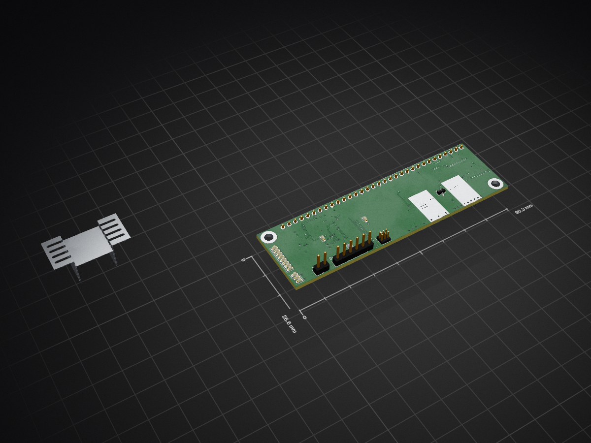
DCC Railcom booster
C12 is an open-source printed circuit board by git4dcc, from the git4dcc/RTB_C12 repository on GitHub, published under the Apache-2.0 licence. It is a 4-layer board of 90.3 × 26.6 mm with 95 parts on 104 nets, routed with 952 tracks and 141 vias.
It is built around the AVR64DA48-E/PT, BD63573NUV-E2 and 74AHC1G08GW, with the LM393, MIC5235-3.3BM5 and BAT54S among its other parts. Its parts include 40 resistors, 19 diodes, 15 capacitors, 9 ICs and 3 connectors.


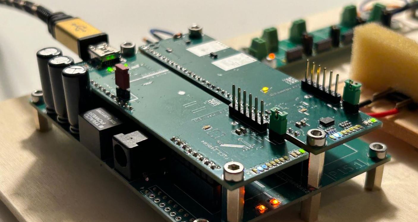
My homebrew RTB C12 Micro Booster implements a booster, DCC generator and Real-time Railcom detector. The booster is optimized for N-scale in respect to track voltage and current.
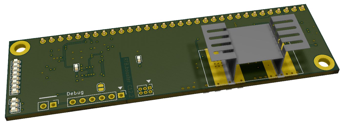
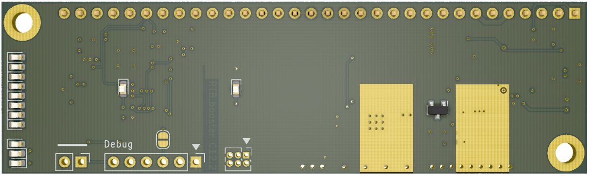
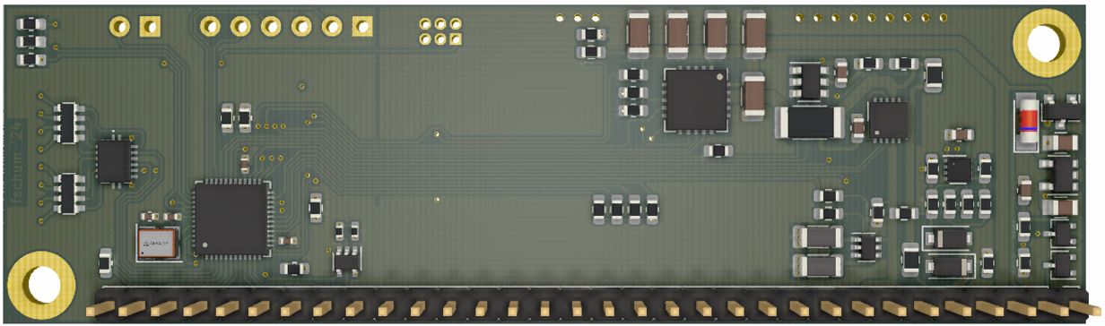
The PCB layout uses SMD footprints with 0.4mm pitch and mostly 0603 parts. Reflow soldering is recommended, but with some experience handsoldering is also possible. Further, the PCB has been optimized for automated assembly (BOM and Position files as CSV).
Filename structure: { pcb }{ code }{ version }.hex
Example: C12F0001.hex
| Description | |
|---|---|
| pcb | Name of matching hardware (C12) |
| code | Type of code contained (R=rom, B=bootloader, F=flash, U=bld update, P=UPDI factory code) |
| version | Release version (####) |
The fuse settings as well as the P-code (C12Pxxxx.hex) has to be installed by using UPDI.
| Fuses Setting |
|---|
| <img src=supplemental/images/C12_fuses.jpg width=500> |
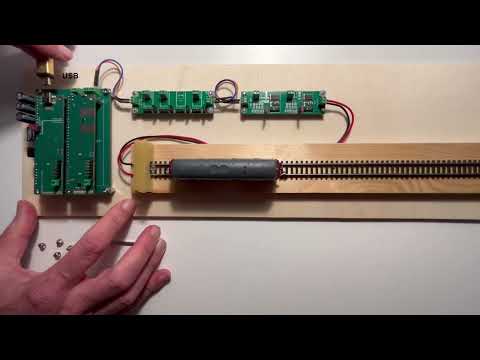
See the C12 booster in action.
This project is intended for hobby use only and is distributed in accordance with the Apache License 2.0 agreement.
| Qty | Value | Footprint | References |
|---|---|---|---|
| 7 | LED_Small | LED_SMD:LED_0603_1608Metric | D14, D32, D33, D34, D35, D36, D37 |
| 6 | 1k | Resistor_SMD:R_0603_1608Metric | R3, R4, R5, R6, R33, R34 |
| 5 | 22uF | Capacitor_SMD:C_1206_3216Metric | C1, C4, C8, C9, C19 |
| 5 | 3.3k | Resistor_SMD:R_0603_1608Metric | R24, R25, R28, R30, R39 |
| 4 | 100nF | Capacitor_SMD:C_0402_1005Metric | C6, C10, C14, C15 |
| 3 | 10k | Resistor_SMD:R_0603_1608Metric | R12, R35, R46 |
| 3 | 220k | Resistor_SMD:R_0603_1608Metric | R13, R18, R27 |
| 3 | 22k | Resistor_SMD:R_0603_1608Metric | R36, R37, R38 |
| 3 | 9.1k | Resistor_SMD:R_0603_1608Metric | R14, R21, R23 |
| 2 | 100k | Resistor_SMD:R_0603_1608Metric | R2, R22 |
| 2 | 100nF | Capacitor_SMD:C_0603_1608Metric | C11, C20 |
| 2 | 10uF | Capacitor_SMD:C_0805_2012Metric | C2, C3 |
| 2 | 1uF | Capacitor_SMD:C_0603_1608Metric | C5, C21 |
| 2 | 3.3k | Resistor_SMD:R_0402_1005Metric | R1, R19 |
| 2 | 300 | Inductor_SMD:L_1206_3216Metric | R26, R32 |
| 2 | 4.7k | Resistor_SMD:R_Array_Convex_4x0603 | RN3, RN4 |
| 2 | 82k | Resistor_SMD:R_0603_1608Metric | R7, R8 |
| 2 | BAT54S | Package_TO_SOT_SMD:SOT-323_SC-70 | D3, D4 |
| 2 | LED | LED_SMD:LED_0603_1608Metric | D8, D16 |
| 2 | MountingHole | MountingHole:MountingHole_3.2mm_M3_ISO7380_Pad | H1, H3 |
| 2 | SS34FA | Diode_SMD:D_SOD-123F | D6, D9 |
| 2 | n.f. | Resistor_SMD:R_0603_1608Metric | R15, R16 |
| 1 | 0.025 | Resistor_SMD:R_2010_5025Metric | R17 |
| 1 | 100 | Resistor_SMD:R_0603_1608Metric | R20 |
| 1 | 10k | Resistor_SMD:R_0805_2012Metric | R31 |
| 1 | 22 | Resistor_SMD:R_0805_2012Metric | R9 |
| 1 | 33k | Resistor_SMD:R_0603_1608Metric | R11 |
| 1 | 4.7k | Resistor_SMD:R_0603_1608Metric | R29 |
| 1 | 56k | Resistor_SMD:R_0603_1608Metric | R10 |
| 1 | 74AHC1G08 | Package_TO_SOT_SMD:SOT-353_SC-70-5 | U1 |
| 1 | 74HC595BQ,115 | Package_DFN_QFN:DHVQFN-16-1EP_2.5x3.5mm_P0.5mm_EP1x2mm | IC3 |
| 1 | ASE-24MHz | Oscillator:Oscillator_SMD_Abracon_ASE-4Pin_3.2x2.5mm | X1 |
| 1 | AVR64DA48 | Package_DFN_QFN:QFN-48-1EP_6x6mm_P0.4mm_EP4.2x4.2mm | U6 |
| 1 | BAT54C | Package_TO_SOT_SMD:SOT-323_SC-70 | D31 |
| 1 | BC847BDW1 | Package_TO_SOT_SMD:SOT-363_SC-70-6 | Q1 |
| 1 | BD63573NUV-E2 | Package_SON:VSON-10-1EP_3x3mm_P0.5mm_EP1.2x2mm | IC1 |
| 1 | Blue | LED_SMD:LED_0603_1608Metric | D13 |
| 1 | D_Schottky_Small | Diode_SMD:D_MiniMELF | D17 |
| 1 | Debug IF | Connector_PinHeader_2.54mm:PinHeader_1x06_P2.54mm_Vertical | J1 |
| 1 | Green | LED_SMD:LED_0603_1608Metric | D5 |
| 1 | Heatsink | Heatsink:Heatsink_AAVID_573300D00010G_TO-263 | HS1 |
| 1 | INA181A1 | Package_TO_SOT_SMD:SOT-23-6 | U3 |
| 1 | Jumper_2_Open | Connector_PinHeader_2.54mm:PinHeader_1x02_P2.54mm_Vertical | JP1 |
| 1 | LED(wht) | LED_SMD:LED_0603_1608Metric | D38 |
| 1 | LM393 | RTB:DFN-8-1EP_NG_2x2mm_Pitch0.5mm | U4 |
| 1 | MCP9700AT-ETT | Package_TO_SOT_SMD:SOT-23 | U15 |
| 1 | MIC5235-3.3 | Package_TO_SOT_SMD:SOT-23-5 | U5 |
| 1 | OPA521 | Package_DFN_QFN:QFN-20-1EP_5x5mm_P0.65mm_EP3.35x3.35mm | U8 |
| 1 | Red | LED_SMD:LED_0603_1608Metric | D12 |
| 1 | Slot Connector | Connector_PinHeader_2.54mm:PinHeader_1x32_P2.54mm_Vertical | J2 |
| 1 | SolderJumper_2_Open | Jumper:SolderJumper-2_P1.3mm_Open_RoundedPad1.0x1.5mm | JP2 |
| 1 | UPDI | Connector_PinHeader_1.27mm:PinHeader_2x03_P1.27mm_Vertical | J3 |
It measures 90.3 × 26.6 mm and has 4 copper layers, 1.6 mm thick.
95 parts, built around the AVR64DA48-E/PT, BD63573NUV-E2, 74AHC1G08GW and LM393. The full list of its parts is on this page, with links to each part's symbol and footprint where PCBKit's library has them.
From the git4dcc/RTB_C12 repository on GitHub, at the commit this page was made from: the board is C12.kicad_pcb and its schematic C12.kicad_sch. PCBKit opens the board in the browser, with nothing to install.
Its repository publishes it under the Apache-2.0 licence: you may reuse it on that licence's terms (keep the author's notice, and for a copyleft licence share your changes alike).

flutterwireless/kicad_conversion
converting the Flutter main boards to KiCAD

azonenberg/triggercrossbar
Rack mountable crossbar matrix for T&M trigger in/out signals, allowing dynamic reconfiguration of an experiment without recabling


azonenberg/misc-devboards
Miscellaneous prototype hardware that wasn't major enough to warrant a dedicated repo

OPRobots/DragonBot2
Siguelíneas de tipo Robotracer para competir en la All Japan Robotracer 2027