Skip to the content
PCBKitNew board
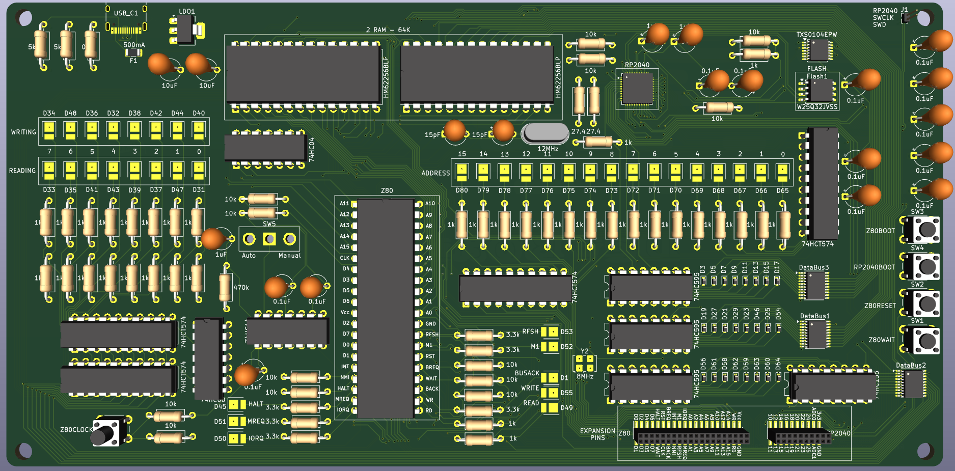
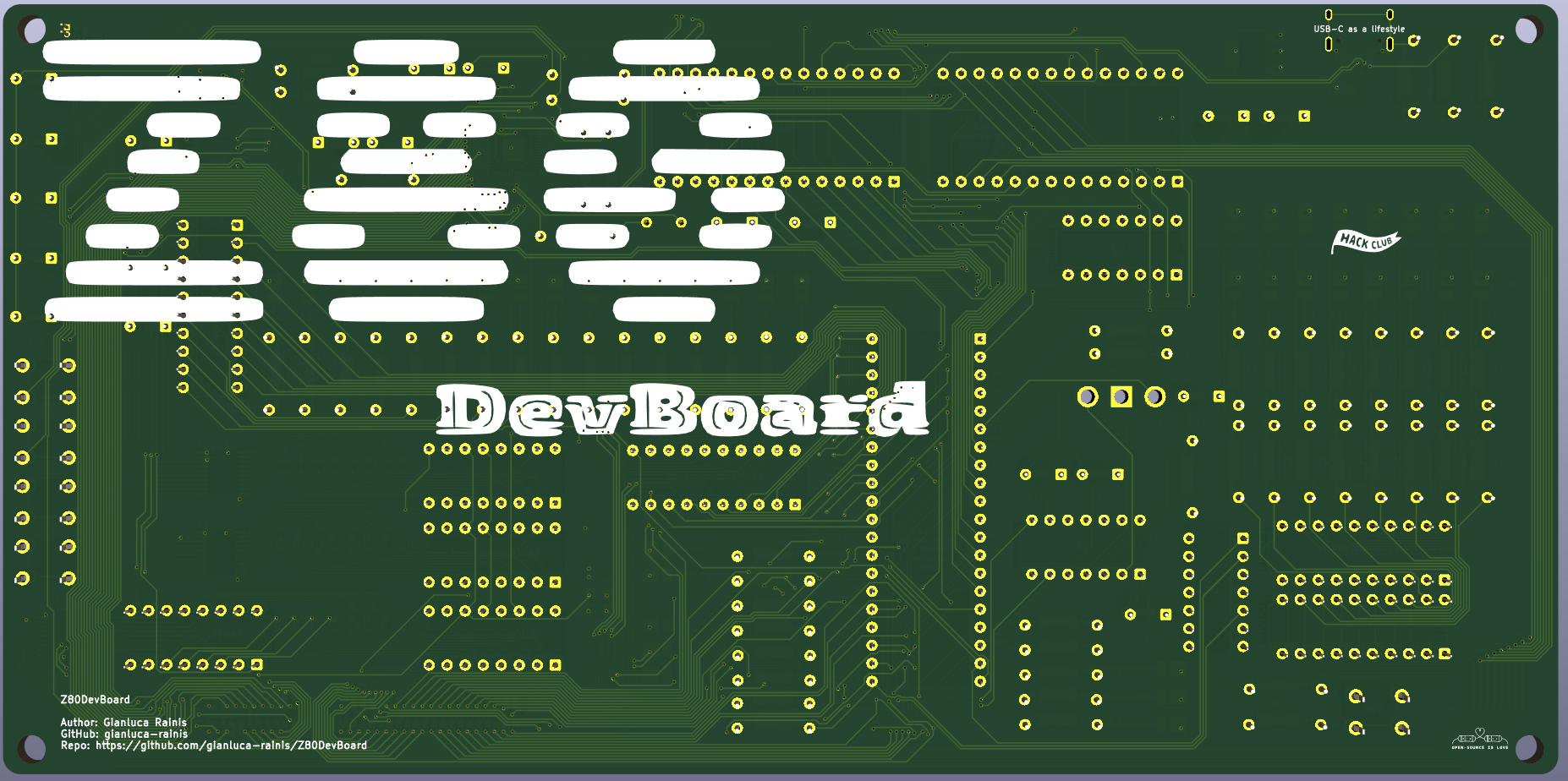
4 layers219 × 108.5 mmZ80DevBoard, the printed circuit board in 3D

An advanced development board for the Z80 microprocessor, powered by an RP2040.

Size
219 × 108.5 mm
Copper layers
4
Thickness
1.6 mm
Parts
182
Nets
237
Pads
834
Tracks, vias
4,193, 439
Pours
1
Routed
Yes
KiCad
KiCad 10.0 (file 20260206)
Created
27 Nov 2025
Updated
8 Oct 2026

Overview

Z80DevBoard is an open-source printed circuit board by gianluca-rainis, from the gianluca-rainis/Z80DevBoard repository on GitHub, published under the CERN-OHL-S-2.0 licence. It is a 4-layer board of 219 × 108.5 mm with 182 parts on 237 nets, routed with 4,193 tracks and 439 vias.

It is built around the RP2040, SN74LVC245APW and W25Q32JVSSIQ, with the 74HC00D, 74HC04D and 74HC14 among its other parts. Its parts include 64 diodes, 61 resistors, 20 capacitors, 6 switches and 4 ICs. It belongs with the microcontroller boards and retro computing and games boards and the RP2040 boards of this library.

Main components

12

README

README.md

Z80DevBoard

Hardware License Software License GitHub Release GitHub Repo stars GitHub watchers Documentation Sponsor

The Z80DevBoard is an advanced development board for the Z80 microprocessor, based on the RP2040.

This board is meant to be a practical educational tool, to help students learn how the Z80, one of the first CPUs and the foundation of all modern ones, works, and how to develop software for it.

To the Z80 is combined a modern RP2040, a powerful microcontroller designed by Raspberry Pi. It allows easy interaction with the board's components: you can load a program for the Z80 into RAM; or establish a serial connection with the computer to perform live operations, such as reading and writing to RAM.

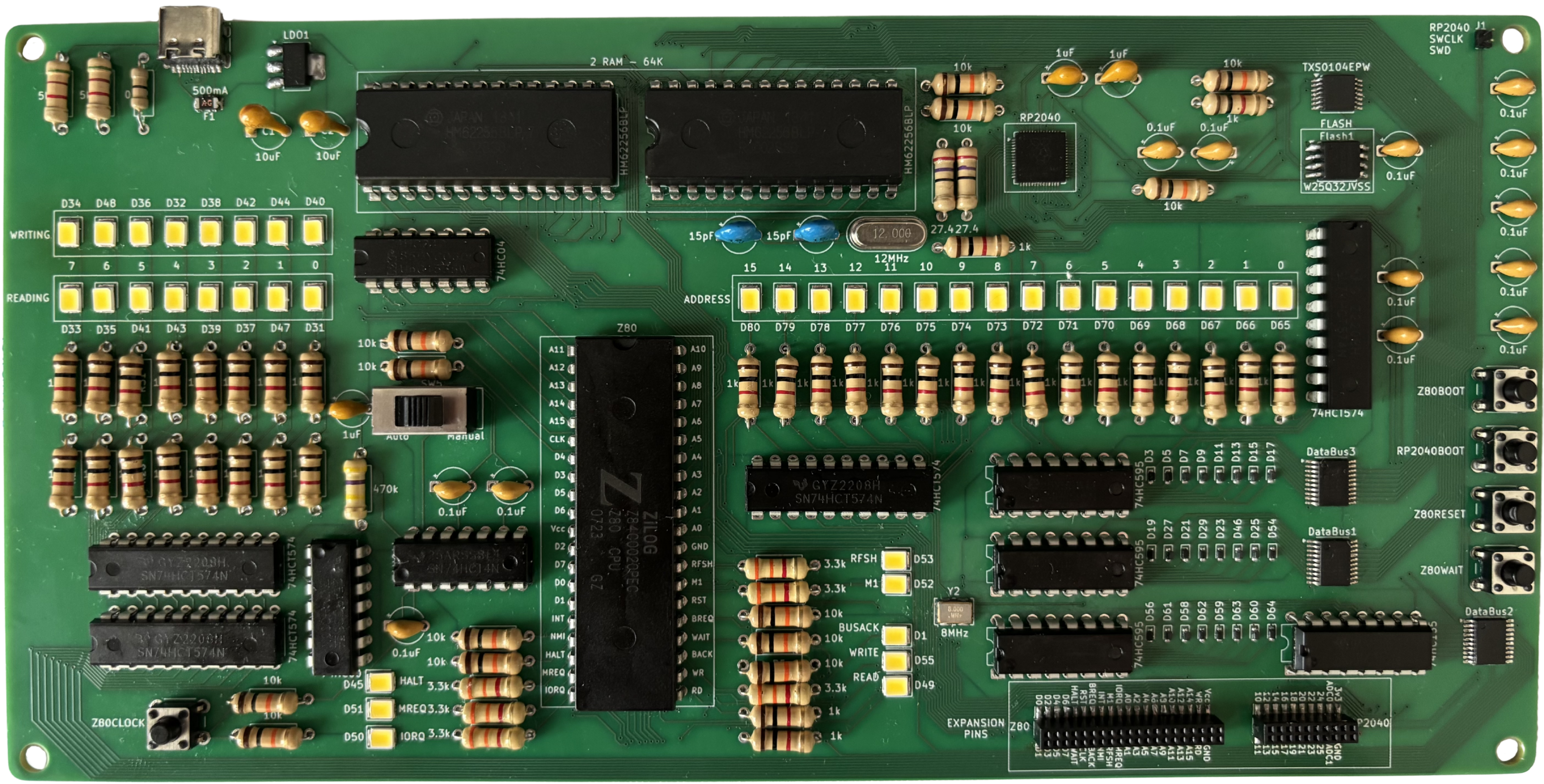
The most educational components of the board are the LED matrices, which provide real-time visual feedback on the Z80's activity. Thanks to these LEDs, you can see which address of the RAM the Z80 is accessing, the byte it's reading or writing, whether it is answering to a BUSREQ with a BUSACK, and essentially all the operations the Z80 is executing.

The board mounts five buttons: the four on the right allow the student to save a Z80 program to flash, load a custom firmware for the RP2040, reset the Z80, and put the Z80 into a wait state. The button on the left sends a manual clock signal to the Z80, in fact, the board mounts a Z84C00 (the CMOS version of the Z80) specifically to allow it to work even with a manual clock.

The board can be connected to a computer through a USB-C port, which provides both power and data transmission. On the bottom-right of the board, are mounted two pin sockets, to support expansion boards or to be used in more advanced projects that require additional hardware.

For more advanced debugging, when testing custom firmware, the SWD and SWCLK pins of the RP2040 are accessible on the top-right of the board.

Front view of the dev board Front view of the dev board
Z80DevBoard Picture

Author

The author of the whole project is: Gianluca Rainis - gianluca-rainis on GitHub.

Sponsor

The PCB prototyping for this project is sponsored by PCBWay.

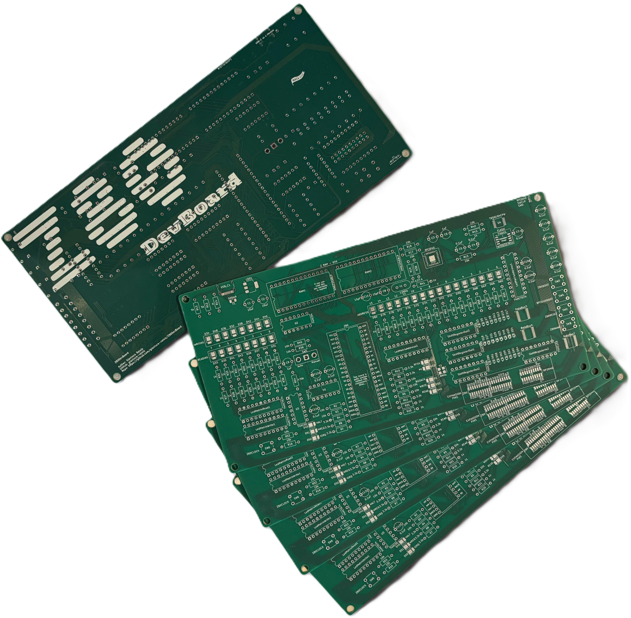
The boards were manufactured with high precision, faithfully following the PCB design down to the smallest details. The silkscreen is crisp and perfectly readable, with no errors or misalignments. The board edges and corner's holes were cut cleanly and accurately. The drill holes match the component footprints exactly, making placement and soldering straightforward. The SMD pads are precise and clean, even for the most challenging footprints, and solder beautifully.

The PCBWay website is intuitive, even for first-time users. Placing an order is simple, and before proceeding to payment the design is reviewed by their technical staff, who catch and communicate any potential manufacturing issues promptly and professionally, avoiding problems before production even begins.

If you are looking for a reliable, high-quality PCB manufacturer for your own projects, PCBWay is highly recommended!

PCBWay

License

Hardware design files (schematics, PCB, BOM):

Licensed under CERN-OHL-S v2.0

Software, firmware and documentation:

Licensed under the MIT License

AI Disclaimer

No AI was used in the conception, design, engineering, or development of this project. Every circuit and every design decision is the original work of the author.

AI tools were used solely as a writing assistant for parts of the documentation, to help refine and organize technical explanations. All content has been reviewed, verified, and edited by the author.

Documentation

The full documentation is available in the docs/ folder.

Development Tools

  • PCB Design: KiCad
  • Documentation and code: Visual Studio Code

PCB Manufacturing

The Gerber files for PCB manufacturing are available in the gerber/ directory.

Project Structure

text
Z80DevBoard/
├── customFootprints.pretty/  # Custom footprints
├── docs/                     # The documentation and the guides
├── firmware/                 # The RP2040 firmware
├── gerber/                   # PCB manufacturing files (Gerber format)
├── images/                   # Documentation images and KiCad symbols
├── .gitattributes            # Gitattributes file
├── .gitignore                # Gitignore file
├── gerber.zip                # Zip folder with all the gerber files
├── Z80DevBoard.kicad_pcb     # PCB layout file
├── Z80DevBoard.kicad_pro     # KiCad project file
├── Z80DevBoard.kicad_sch     # Schematic file
├── Z80DevBoard.step          # 3D model
├── BOM.csv                   # Bill Of Materials
├── CHANGELOG.md              # Change log of the project
├── JOURNAL.md                # Journal of the project
├── LICENSE-CERN-OHL-S.md     # CERN-OHL-S License
├── LICENSE-MIT.md            # MIT License
└── README.md                 # This file

Images

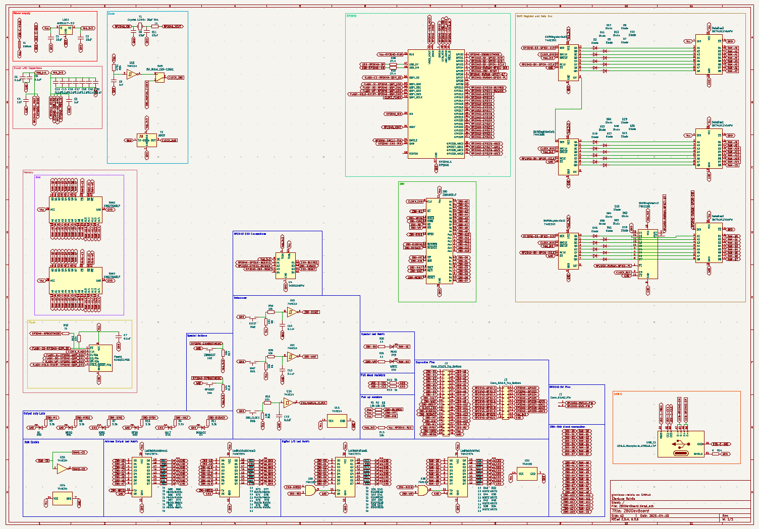
Schematic Diagrams

Complete Schematic (A2 format)
Complete schematic
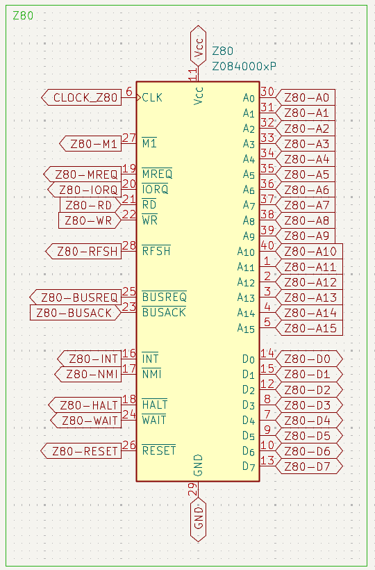
Z80 Section
Z80 subsystem schematic
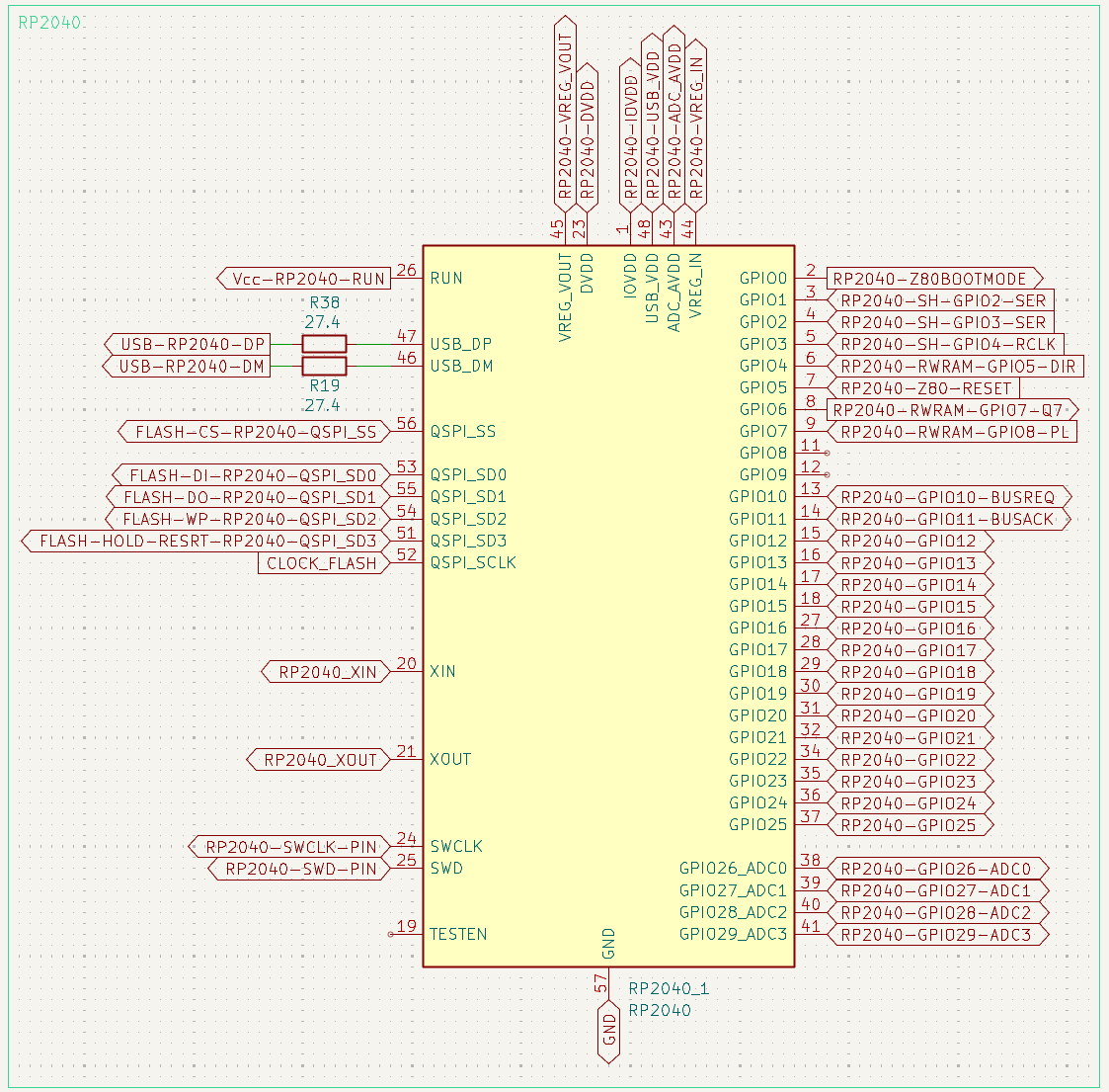
RP2040 Section
RP2040 subsystem schematic

PCB Layout

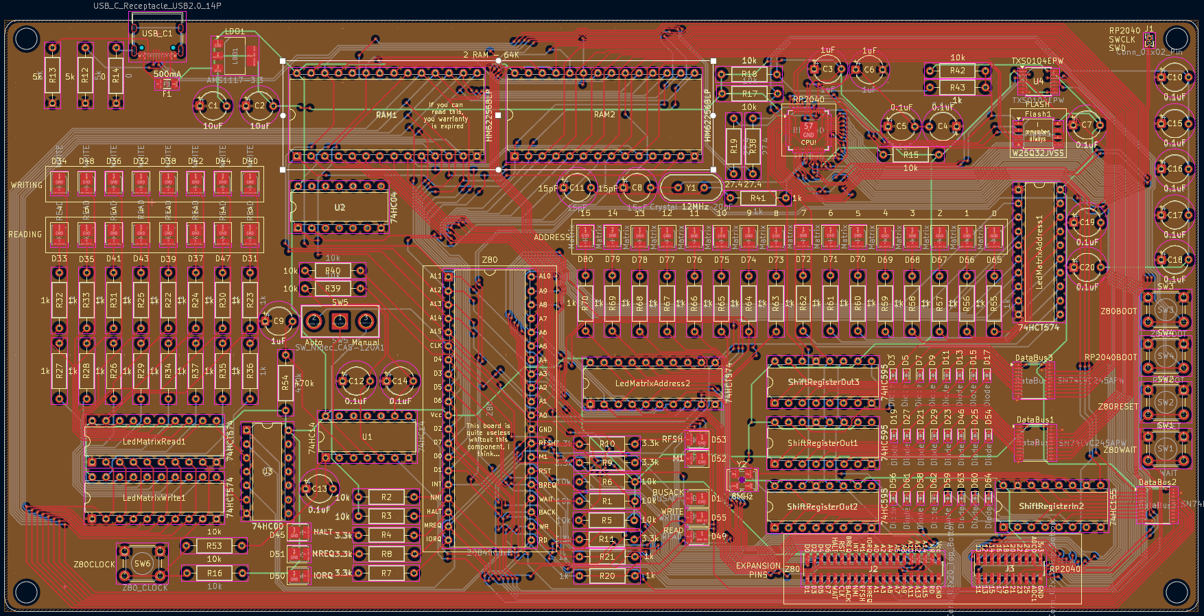
Without Silkscreen
PCB layout without silkscreen
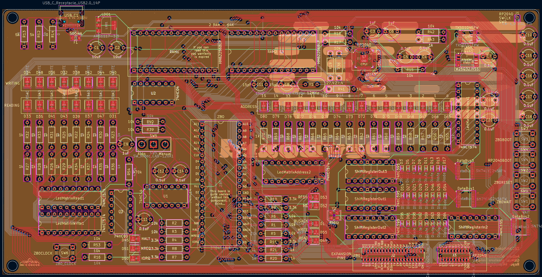
With Silkscreen
PCB layout with silkscreen

3D Renders

Front View
3D render - front view
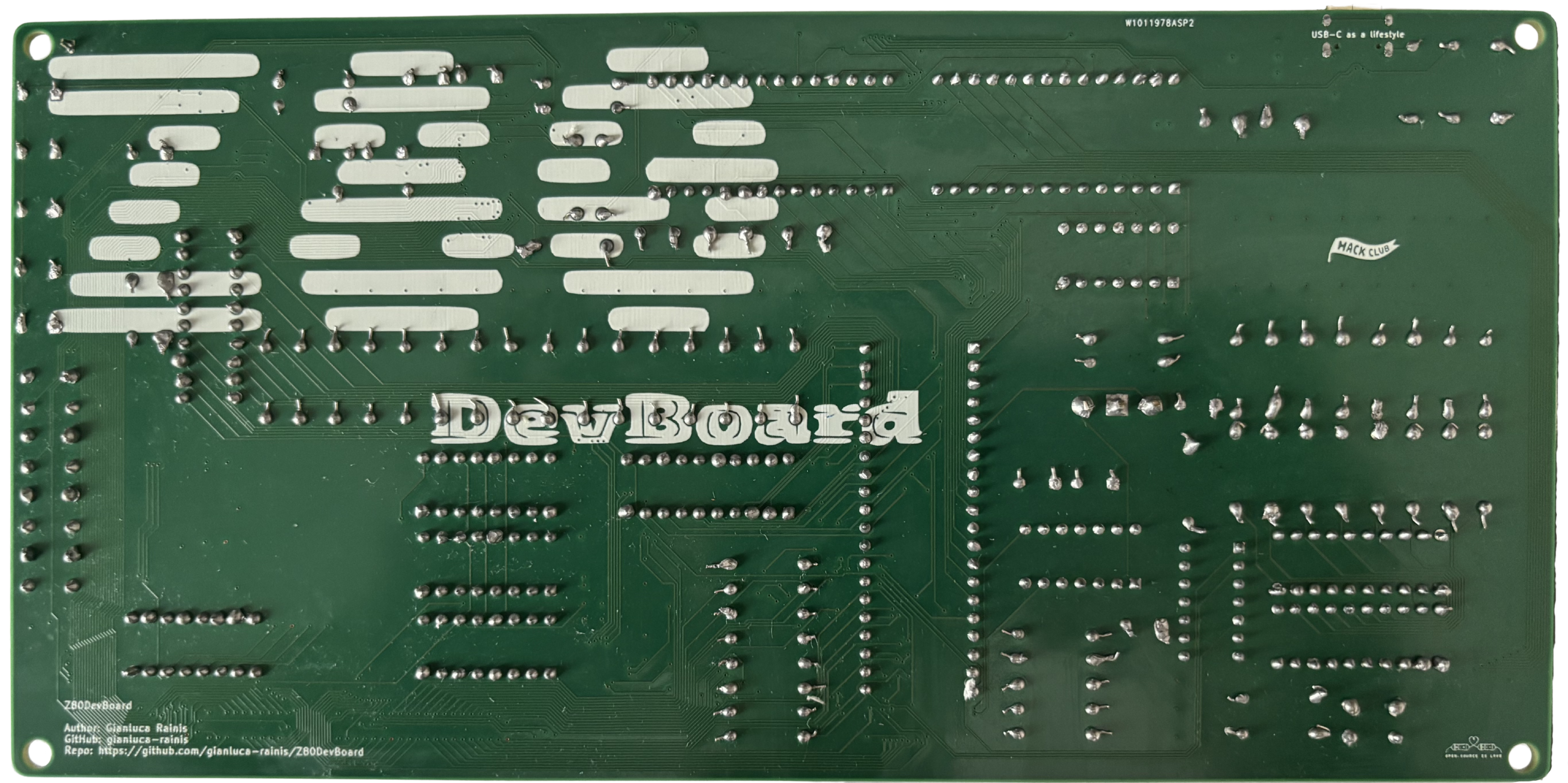
Back View
3D render - back view

Technical Details

  • Size: 219mm x 108.5mm
  • Layers: 4
  • Supply Voltage: 5V, 3v3

Components Table

NameQuantityClassType
Z84C001MicroprocessorThrough Holes
RP20401MicroprocessorSMD
HM62256BLP2MemoryThrough Holes
W25Q32JVSS1MemorySMD
AMS1117-3.31Power ManagementSMD
USB C 2.0 port1Data BusThrough Holes
74HC5953Data BusThrough Holes
74HC1551Data BusThrough Holes
74HCT5744Data BusThrough Holes
SN74LVC245APW3Data BusSMD
TXS0104EPW1Data BusSMD
Connector 2 pins1Data BusThrough Holes
Connector 2×20 pins1Data BusThrough Holes
Connector 2×10 pins1Data BusThrough Holes
Crystal 12MHz 20pF1ClockThrough Holes
Oscillator 8MHz1ClockSMD
74HC141Support componentsThrough Holes
74HC041Support componentsThrough Holes
74HC001Support componentsThrough Holes
Resistor 0 ohm1ResistorThrough Holes
Resistor 27.4 ohm2ResistorThrough Holes
Resistor 1k ohm36ResistorThrough Holes
Resistor 3.3k ohm6ResistorThrough Holes
Resistor 5k ohm2ResistorThrough Holes
Resistor 10k ohm13ResistorThrough Holes
Resistor 470k ohm1ResistorThrough Holes
Capacitors 15pF2CapacitorThrough Holes
Capacitors 0.1uF13CapacitorThrough Holes
Capacitors 1uF4CapacitorThrough Holes
Capacitors 10uF2CapacitorThrough Holes
Button5OtherThrough Holes
Switch1OtherThrough Holes
LED40OtherSMD
Diodes24OtherSMD
Fuse 500mA1OtherSMD

Firmware

Firmware Video Presentation

https://github.com/user-attachments/assets/ee6d8d69-4003-4e21-8f2b-2f08ad0c8d81

Build

From the project root, make sure CMake and the ARM GNU toolchain (arm-none-eabi-gcc) are installed.

If the toolchain is not in your PATH, provide it explicitly with PICO_TOOLCHAIN_PATH:

bash
cmake -S firmware -B firmware/build -DPICO_TOOLCHAIN_PATH=/path/to/arm-gnu-toolchain
cmake --build firmware/build --parallel

If the toolchain is already in your PATH, you can omit PICO_TOOLCHAIN_PATH.

Output file

The file to load in the RP2040's memory after the build is Z80DevBoard.uf2. You can find it in the /firmware/build folder.

You can find more informations about the firmware, including how to write a custom one, in the documentation.

Parts

182
QtyValueFootprintReferences
361kResistor_THT:R_Axial_DIN0207_L6.3mm_D2.5mm_P10.16mm_HorizontalR20, R21, R22, R23, R24, R25, R26, R27, R28, R29, R30, R31, R32, R33, R34, R35 +20
24DiodeDiode_SMD:D_SOD-523D3, D5, D11, D13, D15, D17, D19, D21, D23, D25, D27, D29, D46, D54, D56, D58 +8
16MatrixLED_SMD:LED_PLCC_2835D65, D66, D67, D68, D69, D70, D71, D72, D73, D74, D75, D76, D77, D78, D79, D80
130.1uFCapacitor_THT:CP_Radial_Tantal_D5.0mm_P5.00mmC4, C5, C7, C10, C12, C13, C14, C15, C16, C17, C18, C19, C20
1310kResistor_THT:R_Axial_DIN0207_L6.3mm_D2.5mm_P10.16mm_HorizontalR1, R2, R3, R5, R6, R15, R16, R17, R18, R39, R40, R42, R53
9READLED_SMD:LED_PLCC_2835D31, D33, D35, D37, D39, D41, D43, D47, D49
9WRITELED_SMD:LED_PLCC_2835D32, D34, D36, D38, D40, D42, D44, D48, D55
63.3kResistor_THT:R_Axial_DIN0207_L6.3mm_D2.5mm_P10.16mm_HorizontalR4, R7, R8, R9, R10, R11
474HCT574Package_DIP:DIP-20_W7.62mmLedMatrixAddress1, LedMatrixAddress2, LedMatrixRead1, LedMatrixWrite1
31uFCapacitor_THT:CP_Radial_Tantal_D5.0mm_P5.00mmC3, C6, C9
374HC595Package_DIP:DIP-16_W7.62mmShiftRegisterOut1, ShiftRegisterOut2, ShiftRegisterOut3
3LOGOLOGOG***, G***, G***
3SN74LVC245APWPackage_SO:TSSOP-20_4.4x6.5mm_P0.65mmDataBus1, DataBus2, DataBus3
210uFCapacitor_THT:CP_Radial_Tantal_D5.0mm_P5.00mmC1, C2
215pFCapacitor_THT:CP_Radial_Tantal_D5.0mm_P5.00mmC8, C11
227.4Resistor_THT:R_Axial_DIN0207_L6.3mm_D2.5mm_P10.16mm_HorizontalR19, R38
25kResistor_THT:R_Axial_DIN0207_L6.3mm_D2.5mm_P10.16mm_HorizontalR12, R13
2HM62256BLPPackage_DIP:DIP-28_W15.24mmRAM1, RAM2
10Resistor_THT:R_Axial_DIN0207_L6.3mm_D2.5mm_P10.16mm_HorizontalR14
1470kResistor_THT:R_Axial_DIN0207_L6.3mm_D2.5mm_P10.16mm_HorizontalR54
1500mAFuse:Fuse_1206_3216MetricF1
174HC00Package_DIP:DIP-14_W7.62mmU3
174HC04Package_DIP:DIP-14_W7.62mmU2
174HC14Package_DIP:DIP-14_W7.62mmU1
174HC165Package_DIP:DIP-16_W7.62mmShiftRegisterIn2
1AMS1117-3.3Package_TO_SOT_SMD:SOT-223-3_TabPin2LDO1
1ASCOOscillator:Oscillator_SMD_SiT_PQFN-4Pin_5.0x3.2mmY2
1BUSACKLED_SMD:LED_PLCC_2835D1
1Conn_01x02_PinConnector_PinHeader_1.00mm:PinHeader_1x02_P1.00mm_VerticalJ1
1Conn_02x10_Top_BottomConnector_PinSocket_1.27mm:PinSocket_2x10_P1.27mm_Vertical_SMDJ3
1Conn_02x20_Top_BottomConnector_PinSocket_1.27mm:PinSocket_2x20_P1.27mm_Vertical_SMDJ2
1Crystal 12MHz 20pFCrystal:Crystal_HC49-4H_VerticalY1
1HALTLED_SMD:LED_PLCC_2835D45
1IORQLED_SMD:LED_PLCC_2835D50
1M1LED_SMD:LED_PLCC_2835D52
1MREQLED_SMD:LED_PLCC_2835D51
1RESETButton_Switch_THT:SW_PUSH_6mmSW2
1RFSHLED_SMD:LED_PLCC_2835D53
1RP2040Package_DFN_QFN:QFN-56-1EP_7x7mm_P0.4mm_EP3.2x3.2mmRP2040
1RPBOOTButton_Switch_THT:SW_PUSH_6mmSW4
1SW_Nidec_CAS-120A1customFootprints:SW_Slide-03_Wuerth-WS-SLTVSW5
1TXS0104EPWPackage_SO:TSSOP-14_4.4x5mm_P0.65mmU4
1USB_C_Receptacle_USB2.0_14PConnector_USB:USB_C_Receptacle_HRO_TYPE-C-31-M-12USB_C1
1W25Q32JVSSPackage_SO:SOIC-8_5.3x5.3mm_P1.27mmFlash1
1WAITButton_Switch_THT:SW_PUSH_6mmSW1
1Z084000xPPackage_DIP:DIP-40_W15.24mmZ80
1Z80BOOTButton_Switch_THT:SW_PUSH_6mmSW3
1Z80_CLOCKButton_Switch_THT:SW_PUSH_6mm_H7.3mmSW6

Questions

How big is the Z80DevBoard PCB?

It measures 219 × 108.5 mm and has 4 copper layers, 1.6 mm thick.

What parts does the Z80DevBoard use?

182 parts, built around the RP2040, SN74LVC245APW, W25Q32JVSSIQ and 74HC00D. The full list of its parts is on this page, with links to each part's symbol and footprint where PCBKit's library has them.

Where can I download the Z80DevBoard KiCad files?

From the gianluca-rainis/Z80DevBoard repository on GitHub, at the commit this page was made from: the board is Z80DevBoard.kicad_pcb and its schematic Z80DevBoard.kicad_sch. PCBKit opens the board in the browser, with nothing to install.

Can I use the Z80DevBoard design in my own project?

Its repository publishes it under the CERN-OHL-S-2.0 licence: you may reuse it on that licence's terms (keep the author's notice, and for a copyleft licence share your changes alike).

Similar boards

  • 2 layers235 × 176.5 mmCpu, the printed circuit board in 3D

    Cpu

    Edgeworth/memepu

    cmake -DUSEAFL=yes -DCMAKEBUILDTYPE=Release $PFX/verymeme AFLSKIPCPUFREQ=yes AFLPRELOAD=/usr/local/lib/afl/libdislocator.so \ afl-fuzz -m 1024M -i $PFX/verymeme/testdata/memelang/parsing -o memelangfuzz \ -x…

    286 parts9GPL-3.0
  • 2 layers182 × 138.8 mm-816-board, the printed circuit board in 3D

    -816-board

    snippyrow/-816-board

    A retro computer motherboard for the W65C816S CPU. Dual-core expandable, 16mb extended memory, four expansion ports.

    141 partsMIT
  • 2 layers225.1 × 167.8 mm6502 computer, the printed circuit board in 3D

    6502 computer

    jp0409hlh/6502_computer

    A computer based on Ben Eater's 6502 series

    81 parts7
  • 2 layers137 × 101.1 mmZ80 board1, the printed circuit board in 3D

    Z80 board1

    alexfreed58/z80-CPM-board-with-smart-i-o

    This is yet another retro computer running CPM on an actual Z80 CPU with a twist. Instead of using a traditional UART for communications, it uses a RPi pico module that is no bigger and no more expensive than a UART.

    48 parts2MIT
  • 2 layers306.1 × 130.2 mm8-Bit CPU 32k, the printed circuit board in 3D

    8-Bit CPU 32k

    slu4coder/Minimal-64-Home-Computer

    Legacy: Full TTL-only home computer with VGA and PS/2 and twice the processing power of a Commodore 64

    132 parts94
  • 2 layers100 × 100 mm1802-Mini SPI DMA, the printed circuit board in 3D

    1802-Mini SPI DMA

    arhefner/1802-Mini-SPI-DMA

    SPI Expansion Board for the 1802/Mini Computer

    44 parts2MIT
  • 2 layers99.7 × 99.7 mmRS 232, the printed circuit board in 3D

    RS 232

    cherry-takuan/nlp

    NLP(Nand Logic Processor)のリポジトリ

    61 parts45CC-BY-SA-4.0