2 layers46.5 × 78.5 mm
Shaun proj
SFBdragon/eee3088f-project
Collaborative repo for the UCT EEE3088F Project of team 69.
99 partsCERN-OHL-P-2.0

 giakk/monitor_lamp1
The "intelligence" of the hardware relies on two main modules: an LD2410 presence sensor connected via UART and a VEML7700 ambient light sensor communicating through the I2C protocol.
Monitor lamp custom pcb is an open-source printed circuit board by giakk, from the giakk/monitor_lamp repository on GitHub. It is a 2-layer board of 50 × 35 mm with 35 parts on 39 nets, routed with 137 tracks and 35 vias.
It is built around the TPS5430DDA, AO3401A and AO3400A, with the SS14 and SS34 among its other parts. Its parts include 10 resistors, 9 connectors, 5 capacitors, 3 ICs and 3 transistors. It belongs with the lEDs and displays boards and the ESP32 and RISC-V boards of this library.


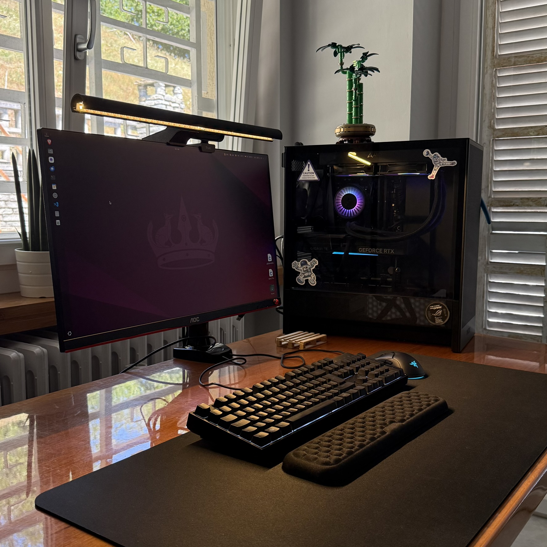
I wanted a smart monitor bar without spending hundreds of euros for something like the BenQ monitor lamp, so I tried to DIY it. Everithing runs on an ESP32-C3 microcontroller, a bit overkill but it will be useful for future upgrade. To control the led, the ESP32 rely on two sensors: a VELM7700 luminosity sensor to dynamically adjusts the leds brightness to maintain optimal lighting conditions, and a LD2410 presense sensor to automatically activates when a user sits.
The system is powered by a 12V input managed via a USB-C Power Delivery (PD) controller, which negotiate with the power supply to ensures 12V for the leds strips. A Mini360 step-down converter reduces this voltage to 5V to power the ESP32-C3 and the sensors, while a dedicated 1.25A fuse protects the entire circuit. The light engine consists of a 12V LED strip driven by an IRLZ44N MOSFET, which allows for precise PWM dimming controlled by the ESP32.
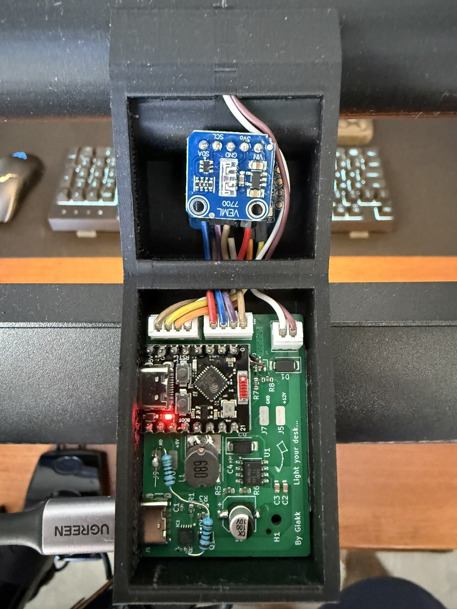
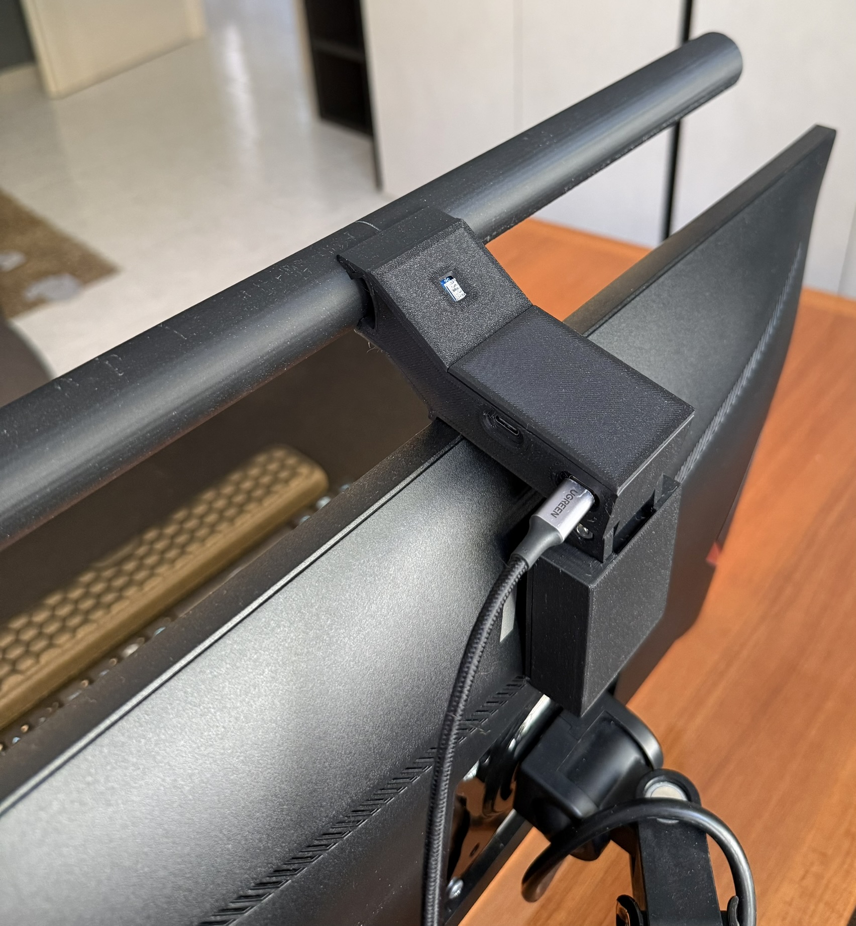
The "intelligence" of the hardware relies on two main modules: an LD2410 presence sensor connected via UART and a VEML7700 ambient light sensor communicating through the I2C protocol. The current prototype, as shown in the images below was updated with the new custom developed PCB board, which info can be found in the Kicad project. (Yeah, I know it is overkill but why no? I wanted to learn to use Kicad and develop my first PCB)
 |  |
|---|
The board has been tested and corrected due to two mistakes I made in the eletrical scheme. First, I hadn't included the ISET resistor for the PD controller, which is essential for negotiating the correct voltage with the charger. Second, I had swapped the drain and source pins of the Q3 MOSFET. Now that everything works as expected, the board project should be correct I you want to produce it.
The firmware is developed within the Arduino framework and utilizes a non-blocking logic to monitor environmental changes in real-time. The core functionality revolves around an adaptive dimming algorithm: the system reads the ambient lux levels via the VEML7700 and applies a square root function to calculate the ideal LED duty cycle. This function actually work like the luminosity on the phone, so it increase if the lux of the room are high, while decrease if there is not light in the room. Maybe it is counterintuitive but it works for me. Change it as you want. To prevent annoying flickering or constant micro-adjustments, the code implements a hysteresis logic, only triggering a brightness transition if the change in light is significant. Furthermore, the integration with the LD2410 mmWave radar allows the lamp to manage power efficiently, executing smooth fade-in and fade-out transitions whenever a user enters or leaves the desk area, ensuring the light is only active when actually needed.
I am working on a version of the software which expose a web page to interact with the light in real time. In the meantime, I uploaded the version of the sketch that actually works the best, with is the sketch_monitor_lamp_working.ino
| Qty | Value | Footprint | References |
|---|---|---|---|
| 6 | Conn_01x01 | Connector_Wire:SolderWirePad_1x01_SMD_1.5x3mm | J4, J5, J7, J8, J9, J10 |
| 2 | 10k | Resistor_SMD:R_0402_1005Metric | R4, R9 |
| 2 | 10uF | Capacitor_SMD:C_0603_1608Metric | C2, C3 |
| 2 | AO3401A | Package_TO_SOT_SMD:SOT-23 | Q1, Q2 |
| 2 | MountingHole | MountingHole:MountingHole_2.2mm_M2 | H1, H2 |
| 1 | 10 | Resistor_SMD:R_0603_1608Metric | R1 |
| 1 | 100k | Resistor_SMD:R_0603_1608Metric | R8 |
| 1 | 100uF | Capacitor_SMD:CP_Elec_5x5.4 | C5 |
| 1 | 10k | Resistor_SMD:R_0603_1608Metric | R5 |
| 1 | 10nF | Capacitor_SMD:C_0402_1005Metric | C4 |
| 1 | 1µF | Capacitor_SMD:C_0402_1005Metric | C1 |
| 1 | 22 | Resistor_SMD:R_0603_1608Metric | R7 |
| 1 | 3.3k | Resistor_SMD:R_0603_1608Metric | R6 |
| 1 | 49.9k | Resistor_SMD:R_0603_1608Metric | R3 |
| 1 | 5.1k | Resistor_SMD:R_0603_1608Metric | R2 |
| 1 | 510 | Resistor_SMD:R_0402_1005Metric | R10 |
| 1 | 68uH | components:L_Sumida_CD75 | L1 |
| 1 | AO3400A | Package_TO_SOT_SMD:SOT-23 | Q3 |
| 1 | ESP32-C3_SUPERMINI_TH | Custom_Sensors:MODULE_ESP32-C3_SUPERMINI_TH | U3 |
| 1 | HUSB238 | Custom_Components:DFN-10L | IC1 |
| 1 | LD2410C_Connection | Connector_JST:JST_PH_B4B-PH-K_1x04_P2.00mm_Vertical | J3 |
| 1 | SS14 | Diode_SMD:D_SMA | D2 |
| 1 | SS34 | Diode_SMD:D_SMA | D1 |
| 1 | TPS5430DDA | Package_SO:TI_SO-PowerPAD-8_ThermalVias | U1 |
| 1 | USB_C_Receptacle_PowerOnly_6P | Connector_USB:USB_C_Receptacle_GCT_USB4125-xx-x_6P_TopMnt_Horizontal | J1 |
| 1 | VEML7700_Connection | Connector_JST:JST_PH_B4B-PH-K_1x04_P2.00mm_Vertical | J2 |
SFBdragon/eee3088f-project
Collaborative repo for the UCT EEE3088F Project of team 69.

Fluepke/Fluepdot
Project for controlling Annax flipdot panels used by the Berliner Verkehrsbetriebe

justinlindh/bramble
Privacy-first LoRa mesh networking for ESP32-S3, built with ESP-IDF


xmyoot/esp32-media-carrier
ESP32 multimedia carrier board with 7–24 V DC buck regulator, 3.2 W Class-D I2S audio amp, WS2812 LED ring driver, and SPI TFT display header


It measures 50 × 35 mm and has 2 copper layers, 1.6 mm thick.
35 parts, built around the TPS5430DDA, AO3401A, AO3400A and SS14. The full list of its parts is on this page, with links to each part's symbol and footprint where PCBKit's library has them.
From the giakk/monitor_lamp repository on GitHub, at the commit this page was made from: the board is monitor_lamp_custom_pcb/monitor_lamp_custom_pcb.kicad_pcb and its schematic monitor_lamp_custom_pcb/monitor_lamp_custom_pcb.kicad_sch. PCBKit opens the board in the browser, with nothing to install.
Its repository states no licence, so its author keeps all rights: ask giakk before reusing the design.