2 layers40.9 × 85 mm
Studio mic
Spirit532/studio_mic
A simple, easy to build preamplifier for any true condenser capsule, to make a condenser microphone
63 parts150MIT

 gallicchio/icepi-zero-dac-adc
Tutorials for Icepi Zero ECP5 FPGA attached to an ADC (AD9280) + DAC (AD9708) Data Acquisition Board
IcepiZero AD9280 AD9708 2x12 is an open-source printed circuit board by gallicchio, from the gallicchio/icepi-zero-dac-adc repository on GitHub. It is a 2-layer board of 65 × 30 mm with 10 parts on 20 nets, routed with 76 tracks and 0 vias.
It is built around the M2.5. Its parts include 2 capacitors and 2 connectors. It belongs with the fPGA and programmable logic boards of this library.
A passive 65 × 30 mm board that connects an Icepi Zero's 40-pin header to the AD9280/AD9708 converter module with a 2×12 header and SMA connectors (the one in the tutorial's photo).
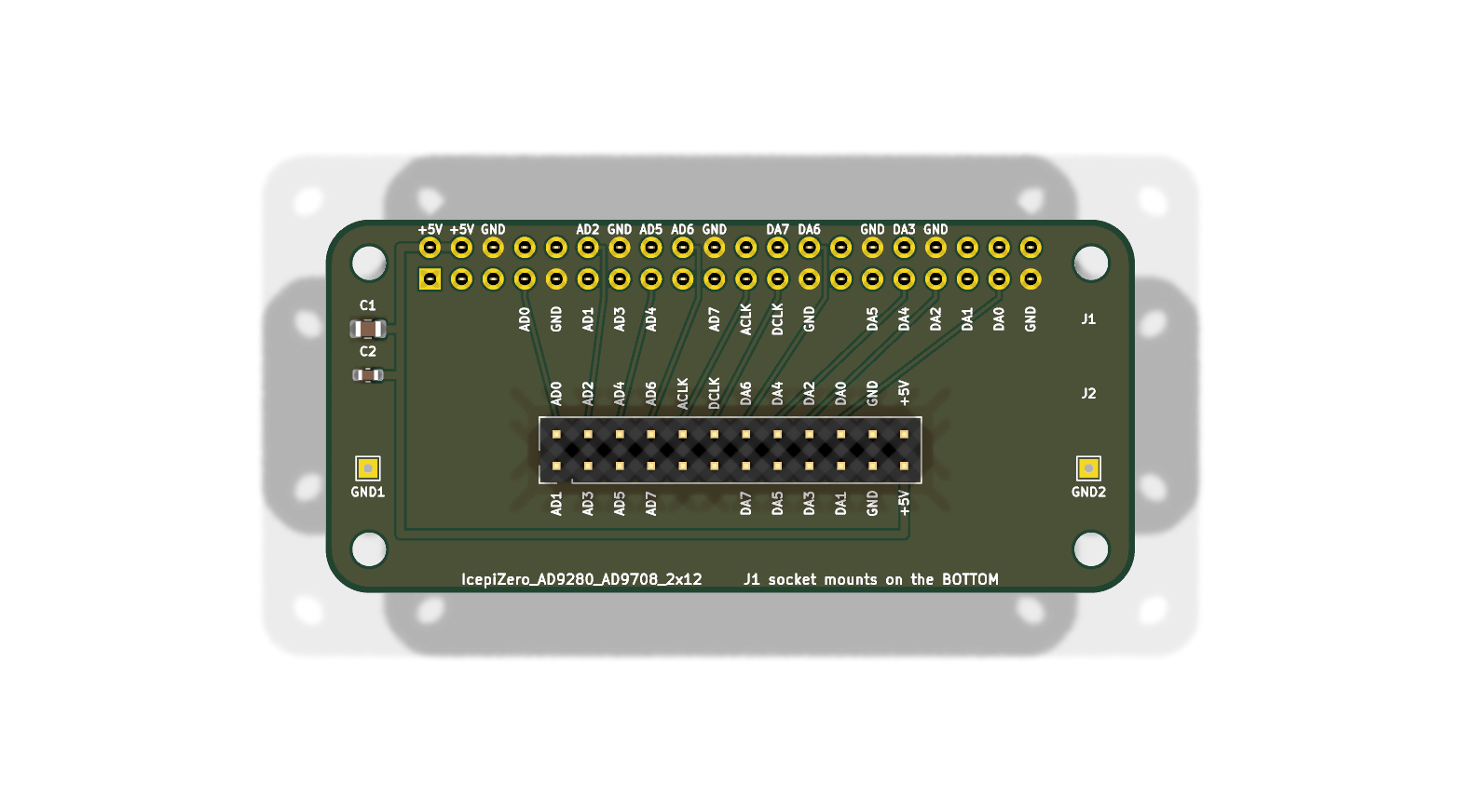
Upload IcepiZero_AD9280_AD9708_2x12-gerbers.zip to a PCB maker such as
JLCPCB, keep the defaults (2 layers, 1.6 mm, any
colour), and ask for as many boards as you need. Five cost about $2 plus
shipping.
Then solder on:
| part | what | where |
|---|---|---|
| J1 | 2×20 female socket, 2.54 mm | on the bottom: it takes the Icepi Zero's 40-pin header |
| J2 | 2×12 male header, 2.54 mm | on the top, pins up: the module's socket plugs onto it |
| C1, C2 | 10 µF (0805) and 100 nF (0603) capacitors | the module's 5 V supply; optional |
| GND1, GND2 | plated holes | for a wire to the module's own ground, if you want a better ground return than the headers give |
The adapter has the Icepi Zero's shape, and the mounting holes of the two line up. Plug the Icepi Zero in so that they do. The wrong way round puts 5 V on FPGA pins.
The module goes on top. Every pin of both connectors is named on the
silkscreen, with the same names the module uses (AD0...AD7 and ACLK for the
ADC, DA0...DA7 and DCLK for the DAC), so line the module's labels up with
J2's.
The KiCad 10 project (.kicad_pro, .kicad_sch, .kicad_pcb), the schematic
as a PDF, the gerbers, a picture, and the pin map:
| module pin | design name | Icepi Zero header pin | Raspberry Pi name | ECP5 ball |
|---|---|---|---|---|
| AD0 ... AD7 | adc_d[0] ... adc_d[7] | 7, 11, 12, 13, 15, 16, 18, 19 | GPIO4, 17, 18, 27, 22, 23, 24, 10 | R1, R3, N4, P3, P2, M2, L1, L2 |
| ACLK | adc_clk | 21 | GPIO9 | J1 |
| DCLK | dac_clk | 23 | GPIO11 | G2 |
| DA7 ... DA0 | dac_d[7] ... dac_d[0] | 24, 26, 29, 31, 32, 33, 35, 37 | GPIO8, 7, 5, 6, 12, 13, 19, 26 | H2, G1, E1, F3, J3, E3, E4, D4 |
The pin assignment stays off the six Raspberry Pi GPIOs that a real Pi can't lend out (the HAT ID pins, I2C1 with its fixed pull-ups, and the serial console), so the same adapter and module also plug into a Raspberry Pi, for a much slower version of the same experiments.
The boards were drawn by a script, and the .kicad_pcb files are the source
of truth. The gerbers were plotted on 2026-09-14; plot new ones with KiCad
(File → Fabrication Outputs) if you change anything.
| Qty | Value | Footprint | References |
|---|---|---|---|
| 4 | M2.5 | MountingHole_2.7mm_M2.5_ISO7380 | H1, H2, H3, H4 |
| 2 | GND | TestPoint_THTPad_1.5x1.5mm_Drill0.7mm | GND1, GND2 |
| 1 | 100nF | C_0603_1608Metric | C2 |
| 1 | 10uF/16V | C_0805_2012Metric | C1 |
| 1 | HS-AD/DA V2.0 AD9280 ADC + AD9708 DAC | PinHeader_2x12_P2.54mm_Vertical | J2 |
| 1 | Icepi Zero GPIO | PinSocket_2x20_P2.54mm_Vertical | J1 |
Spirit532/studio_mic
A simple, easy to build preamplifier for any true condenser capsule, to make a condenser microphone


gmcn42/clumsyMIDI
A THT-only Raspberry Pi expansion board containing a MIDI interface, DAC, and OLED display

DvidMakesThings/HW_PDNode-600-Pro
The PDNode-600 is a professional-grade, 600W USB Power Delivery Unit designed specifically for compact 10-inch rack systems, targeting embedded developers, homelab enthusiasts, test benches, and smart infrastructure.


Zebra-Rodeo/marelleo
Une boîte qui raconte une histoire quand on pose une figurine dessus. Boîtier, carte, micrologiciel et doc pour la refaire.

dsanchezseco/punk75
Ortholinear keyboard with 75 keys and all components through hole
It measures 65 × 30 mm and has 2 copper layers, 1.6 mm thick.
10 parts, built around the M2.5. The full list of its parts is on this page, with links to each part's symbol and footprint where PCBKit's library has them.
From the gallicchio/icepi-zero-dac-adc repository on GitHub, at the commit this page was made from: the board is adapter_board/IcepiZero_AD9280_AD9708_2x12.kicad_pcb and its schematic adapter_board/IcepiZero_AD9280_AD9708_2x12.kicad_sch. PCBKit opens the board in the browser, with nothing to install.
Its repository states no licence, so its author keeps all rights: ask gallicchio before reusing the design.