4 layers96 × 172 mm

 G-EDM/Gapstorm-Pro3
G-EDM Gapstorm Pro - Pulseboard PCB files including BoM, Kicad files, Gerber files and Pick&Place file
Gapstorm retro is an open-source printed circuit board by G-EDM, from the G-EDM/Gapstorm-Pro repository on GitHub. It is a 4-layer board of 99.8 × 99.8 mm with 137 parts on 57 nets, routed with 274 tracks and 422 vias.
It is built around the OPA607QDBVRQ1, INA293B3QDBVRQ1 and IXDI614SI, with the HCNR201-500E, 6N137S and CL21B106KAYQNNE among its other parts. Its parts include 60 capacitors, 36 resistors, 15 diodes, 11 ICs and 7 connectors. It belongs with the retro computing and games boards of this library.


 ______     _______ ______  _______
|  ____ ___ |______ |     \ |  |  |
|_____|     |______ |_____/ |  |  |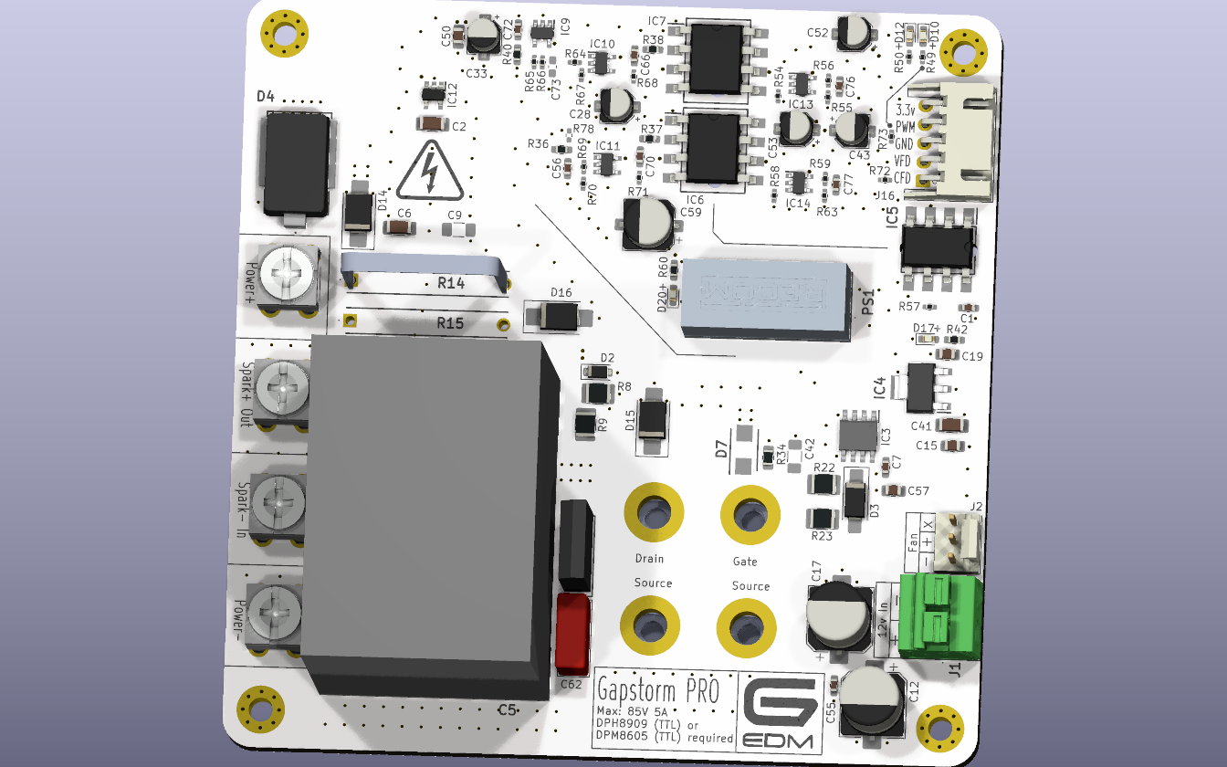
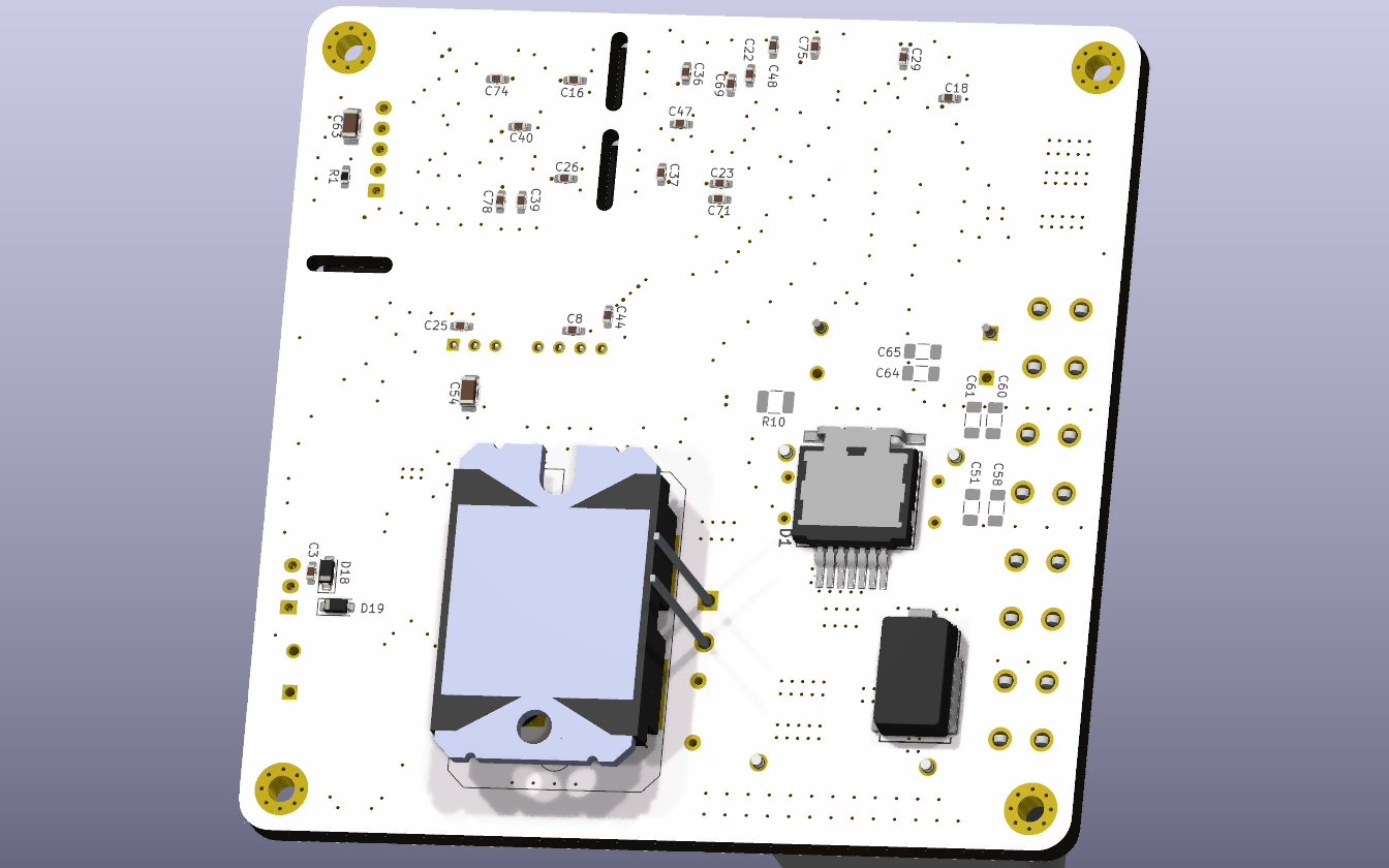
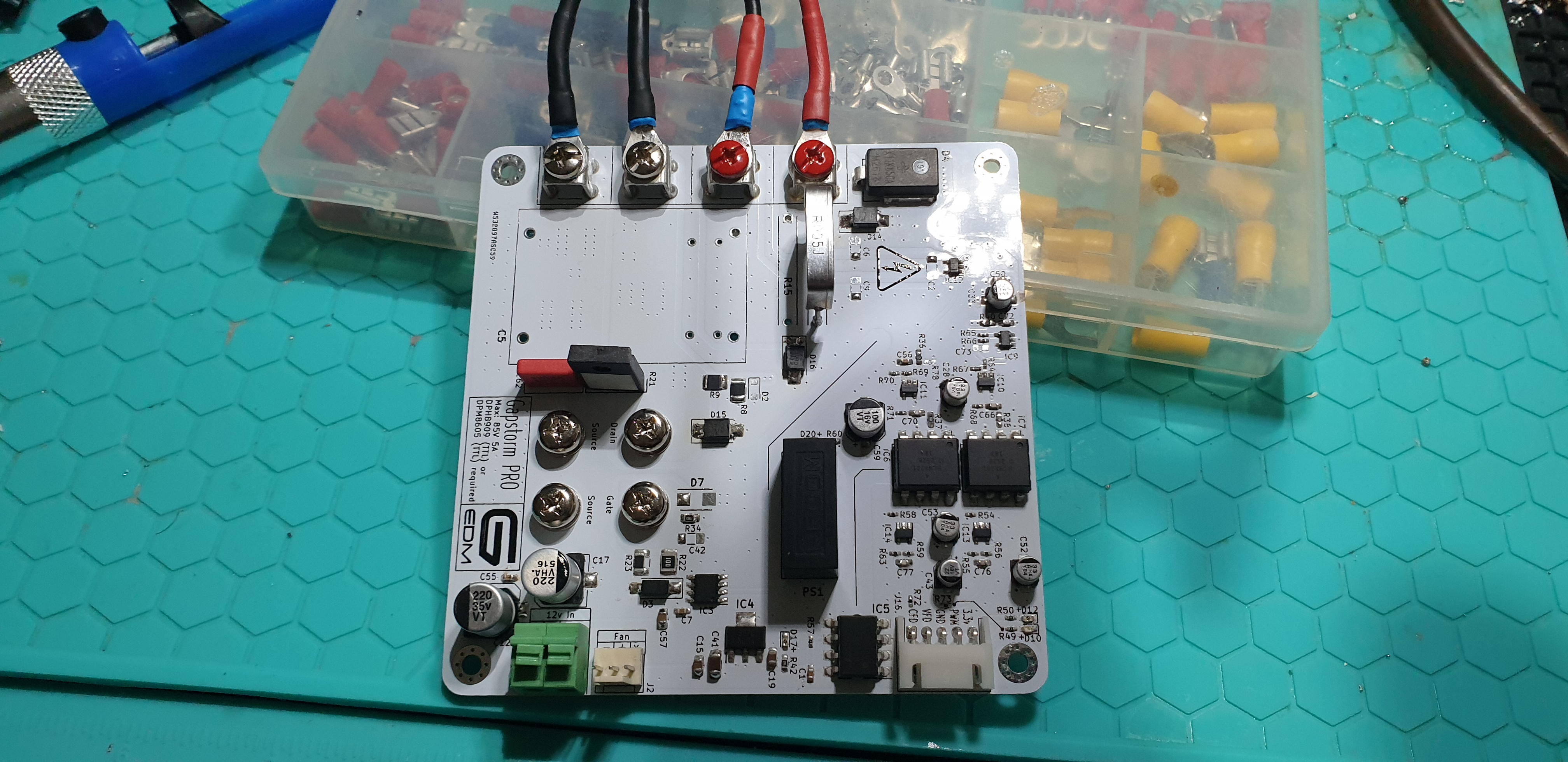
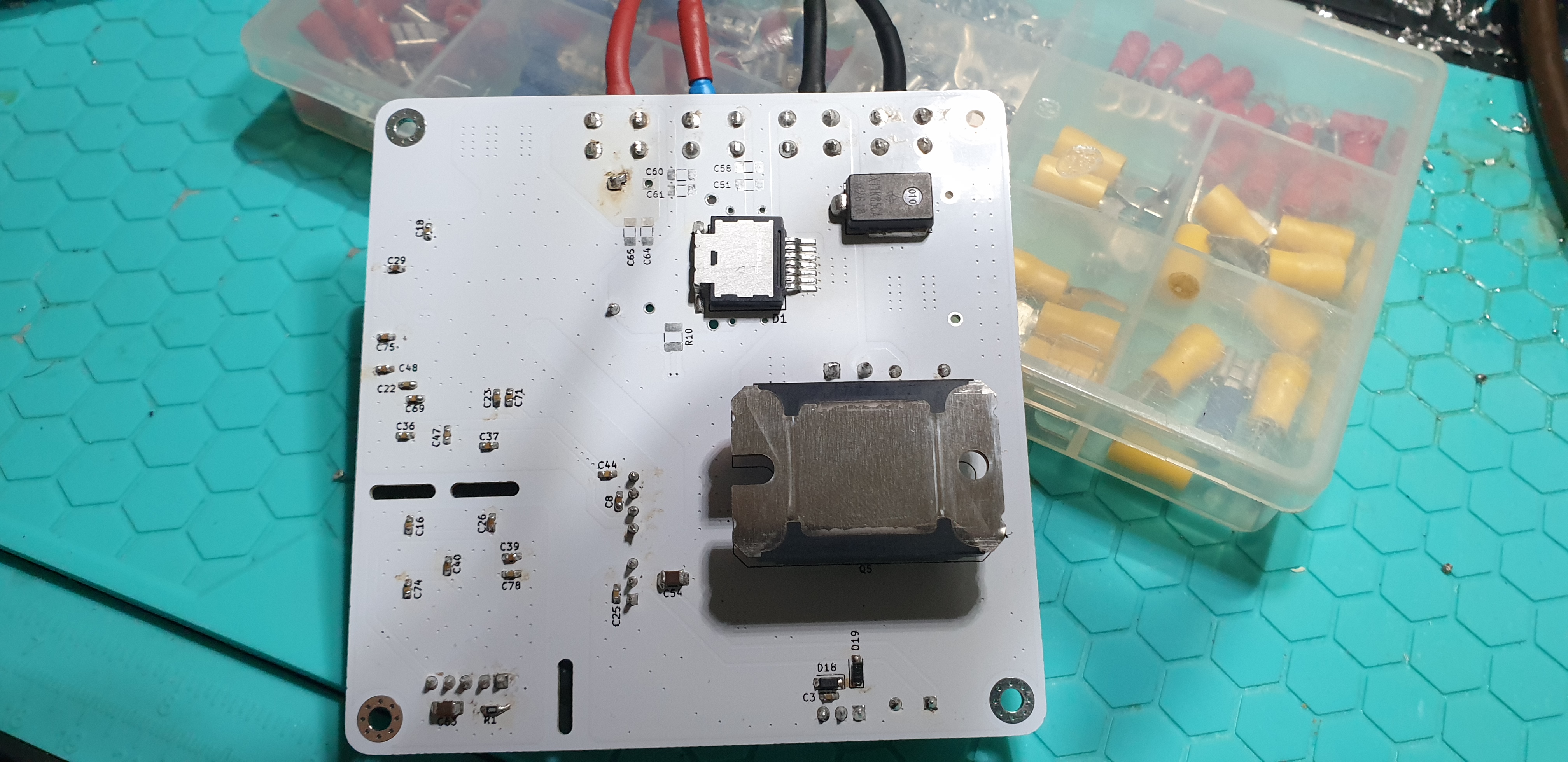
The files provided on this repo are fully OpenSource. Have fun. No warranties!
I just made an initial test for max current without risking the big FET. Connected two parallel IRFP260N to the screw terminals of the board and was able to push 9.5A without breaking anything.
The big FET has a much lower RDSon resistance so there is still a chance that it may not take the full 9.5A but this looks very good so far. No warranty on that but I think the big FET will also be able to manage the full DPH8909 current.
This repo contains the upgrade Gapstorm PCB files. I already assembled the board but did not yet had time for real tests. I made a short test shorting the wires at 2.5A and everything looked good. Feedback was very nice. Once I'm done testing, a link to PCBway will be provided and the max current rating published too. For people that have the initial Gapstorm PCB I recommend to change the Gate resistor against a 100R resistor as it is on this board. The Mosfet switching happens so rapid that very high inrush currents can occur that can damage the FET. Even with the 100R resistor the Mosfet is very very fast switching without visible slope on the ESP scope.
The board is able to carry significant currents and there are two components that require a cooling solution. The Mosfet requires a heatsink. it can be screwed without isolation barrier to a heatsink. The Mosfets exposed metal body is not internally connected and isolation is not needed. Thermal paste should be placed between the FET and the Heatsink. But also the big freewheeling diode (STTH60RQ06L2Y) requires cooling. It is not the same height as the Mosfet so there needs to be a little metal pad to fill the space between diode and heatsink. The diode exposed metal cover is internally connected and therefore a little isolation pad is required between the diode and the shimming block. If for some reason it is not possible to cool the diode it would also be ok to just remove it.
Max input voltage on the power inputs is designed to be 80V. The board has TVS and Zener protection diodes and the input should not exceed 80v. 70V is my personal sweetspot.
In regards of max current there is still some research that needs to be done. Depending on the Gate resistor and the Foil cap there can occur very high inrush currents that can easily destroy the Mosfet. I changed the Gate resistor to a higher value to prevent this from easily happening but have not produced real max rating data as of now. The Mosfet is expenssive and I am too broke to burn through things. I'm working on that.
The board requires a 5P JST XH wire to connect with the motionboard
A little 12v PSU is required for the gate drive. I use a Mean Well APV-35-12 LED 12V 2.4A for that.
DPM/DPH positive output connects to Power+ and negative to Power-. Note that those terminals are not next to eachother on this board.
The two center terminals are the spark terminals. Spark+ connects to the work and Spark- to the electrode.
The Mosfet requires good cooling. It can be screwed onto a heatsick or inside a metal enclosure with the PCB just sitting on top of it. No isolation barrier between the Mosfet and the colling component is required as the SOT227 Package already provides isolation.
The switching section is a low side switch and thereforewhile the Mosfet is active DRAIN is switched to GND The voltage feedback is measured from Work to Electrode using a voltage divider to scale the voltage down and feed it into a sensing circuit. The nature of this makes a measurement in the OnTime of the switching impossible since the voltage drops close to GND and the input for the sensing circuit looks like a squarewave. This allows proximity sensing but not real gap voltage sensing and then OnTime requires to be filtered out via software.
One of those devices is required as source for the spark. I recommend the DPH8909 as it allows higher voltages but the DPM8605 is ok too but limited to 60V.
Those step down converters come with different interfaces. In order to connect them to the motionboard and have the firmware communicate with them the TTL version is required. Not the RF (Radio) or RS485! Also the baudrate needs to be set at the highest available to match the baudrate used in the firmware. See the manual for the device and search for BAUD. 115200 is what it needs to be and this number is shown on the little display as 115.2 or something.
Set the current to 1.6A or 1.8A before the first run. This is normally the current I use and safe. Voltage either 70v or if the DPM8605 is used 60v.
A little Wiki can be found here
| Qty | Value | Footprint | References |
|---|---|---|---|
| 24 | 885012206095 | Capacitor_SMD:C_0603_1608Metric_Pad1.08x0.95mm_HandSolder | C1, C3, C16, C18, C22, C23, C25, C26, C29, C36, C37, C39, C40, C44, C47, C48 +8 |
| 8 | DNP | Capacitor_SMD:C_1206_3216Metric_Pad1.33x1.80mm_HandSolder | C9, C42, C51, C58, C60, C61, C64, C65 |
| 5 | OPA607QDBVRQ1 | kicad-models:SOT95P280X145-5N | IC9, IC10, IC11, IC13, IC14 |
| 4 | 560112110019 | Resistor_SMD:R_0402_1005Metric_Pad0.72x0.64mm_HandSolder | R54, R58, R68, R71 |
| 4 | C0603C100F5HACAUTO | Capacitor_SMD:C_0603_1608Metric_Pad1.08x0.95mm_HandSolder | C66, C70, C76, C77 |
| 4 | CL21B106KAYQNNE | Capacitor_SMD:C_0805_2012Metric_Pad1.18x1.45mm_HandSolder | C15, C19, C50, C57 |
| 4 | ERJ-H2RD2002X | Resistor_SMD:R_0402_1005Metric_Pad0.72x0.64mm_HandSolder | R55, R56, R59, R63 |
| 4 | MountingHole | MountingHole:MountingHole_3.2mm_M3_Pad_Via | H1, H2, H3, H4 |
| 3 | 150060VS83000 | LED_SMD:LED_0603_1608Metric_Pad1.05x0.95mm_HandSolder | D12, D17, D20 |
| 3 | AVS226M16B12T-F | Capacitor_SMD:CP_Elec_4x5.4 | C28, C33, C43 |
| 3 | CRCW04020000Z0EDHP | Resistor_SMD:R_0402_1005Metric_Pad0.72x0.64mm_HandSolder | R66, R72, R73 |
| 3 | ERJ-PA2D1002X | Resistor_SMD:R_0402_1005Metric_Pad0.72x0.64mm_HandSolder | R57, R64, R69 |
| 3 | SMBJ5378B-TP | Diode_SMD:D_SMB_Handsoldering | D14, D15, D16 |
| 2 | 1N4148W-7-F | Diode_SMD:D_SOD-123 | D18, D19 |
| 2 | 560112116053 | Resistor_SMD:R_0603_1608Metric_Pad0.98x0.95mm_HandSolder | R42, R60 |
| 2 | 7691-2 | kicad-models:8191SEMS | J5, J6 |
| 2 | CRCW0603249RFKEAHP | Resistor_SMD:R_0603_1608Metric_Pad0.98x0.95mm_HandSolder | R37, R38 |
| 2 | C_Polarized | Capacitor_THT:C_Radial_D12.5mm_H25.0mm_P5.00mm | C4, C10 |
| 2 | EEE-HAA330WAR | Capacitor_SMD:CP_Elec_4x5.4 | C52, C53 |
| 2 | EEE-HAV221UAP | Capacitor_SMD:CP_Elec_8x10.5 | C12, C17 |
| 2 | ERJ-PA2D2200X | Resistor_SMD:R_0402_1005Metric_Pad0.72x0.64mm_HandSolder | R49, R50 |
| 2 | ERJ-PA2D4701X | Resistor_SMD:R_0402_1005Metric_Pad0.72x0.64mm_HandSolder | R67, R70 |
| 2 | GRT31CC71E226ME13K | Capacitor_SMD:C_1206_3216Metric_Pad1.33x1.80mm_HandSolder | C41, C54 |
| 2 | HCNR201-500E | custom:SOP254P1230X400-8N | IC6, IC7 |
| 2 | XFD11K85CA-M3/I | kicad-models:SM8A27HE32D | D4, D5 |
| 1 | 1792863 | kicad-models:1792863 | J1 |
| 1 | 22-11-2037 | Connector:FanPinHeader_1x03_P2.54mm_Vertical | J2 |
| 1 | 560112120013 | Resistor_SMD:R_0805_2012Metric_Pad1.20x1.40mm_HandSolder | R34 |
| 1 | 6N137S | custom:SOP254P1016X460-8N | IC5 |
| 1 | 7691-3 | kicad-models:8191SEMS | J8 |
| 1 | 7691-4 | kicad-models:8191SEMS | J7 |
| 1 | 885012206077 | Capacitor_SMD:C_0603_1608Metric_Pad1.08x0.95mm_HandSolder | C72 |
| 1 | 885012206083 | Capacitor_SMD:C_0603_1608Metric_Pad1.08x0.95mm_HandSolder | C56 |
| 1 | 885012208019 | Capacitor_SMD:C_1206_3216Metric_Pad1.33x1.80mm_HandSolder | C63 |
| 1 | 885342008004 | Capacitor_SMD:C_1206_3216Metric_Pad1.33x1.80mm_HandSolder | C2 |
| 1 | 885382208014 | Capacitor_SMD:C_1206_3216Metric_Pad1.33x1.80mm_HandSolder | C6 |
| 1 | APT1608LVBC/D | LED_SMD:LED_0603_1608Metric_Pad1.05x0.95mm_HandSolder | D10 |
| 1 | AVS107M16D16T-F | Capacitor_SMD:CP_Elec_6.3x5.4 | C59 |
| 1 | B360A-E3/61T | Diode_SMD:D_SMA_Handsoldering | D3 |
| 1 | BZT52B6V2 | Diode_SMD:D_SOD-123F | D2 |
| 1 | C4AQLBW5700A3LK | kicad-models:C4AQLBW5700A3LK | C5 |
| 1 | CRCW06030000Z0EAHP | Resistor_SMD:R_0603_1608Metric_Pad0.98x0.95mm_HandSolder | R40 |
| 1 | CRCW0603200RFKEAHP | Resistor_SMD:R_0603_1608Metric_Pad0.98x0.95mm_HandSolder | R36 |
| 1 | CRCW1210100RFKEAHP | Resistor_SMD:R_1210_3225Metric_Pad1.30x2.65mm_HandSolder | R22 |
| 1 | CRCW121010K0FKEAHP | Resistor_SMD:R_1210_3225Metric_Pad1.30x2.65mm_HandSolder | R9 |
| 1 | CRCW121010R0FKEAHP | Resistor_SMD:R_1210_3225Metric_Pad1.30x2.65mm_HandSolder | R23 |
| 1 | CRCW1210620RFKEAHP | Resistor_SMD:R_1210_3225Metric_Pad1.30x2.65mm_HandSolder | R8 |
| 1 | DNP | Resistor_SMD:R_0402_1005Metric_Pad0.72x0.64mm_HandSolder | R78 |
| 1 | DNP | kicad-models:MSR50R1F1 | R15 |
| 1 | DNP | Capacitor_SMD:C_0603_1608Metric_Pad1.08x0.95mm_HandSolder | C73 |
| 1 | DNP | Resistor_SMD:R_1210_3225Metric_Pad1.30x2.65mm_HandSolder | R10 |
| 1 | ERJ-PA3F2000V | Resistor_SMD:R_0603_1608Metric_Pad0.98x0.95mm_HandSolder | R1 |
| 1 | INA293B3QDBVRQ1 | kicad-models:SOT95P280X145-5N | IC12 |
| 1 | IXDI614SI | kicad-models:SOIC127P600X170-9N | IC3 |
| 1 | IXFN230N20T | Package_TO_SOT_THT:SOT-227 | Q5 |
| 1 | LM7805MPX_NOPB | kicad-models:SOT230P700X180-4N | IC4 |
| 1 | LOGO | graphics:warning-high-voltage-10mm | G*** |
| 1 | LOGO | Schreibtisch:gedm-new-logo-smalladfabvbb | G*** |
| 1 | LTO030F10R00JTE3 | kicad-models:TO508P350X1040X2030-2P | R21 |
| 1 | MKP4J021002B00KSSD | Capacitor_THT:C_Rect_L10.0mm_W4.0mm_P7.50mm_MKS4 | C62 |
| 1 | MSR5-0R005J1 | kicad-models:MSR50R1F1 | R14 |
| 1 | RCS04021K00FKED | Resistor_SMD:R_0402_1005Metric_Pad0.72x0.64mm_HandSolder | R65 |
| 1 | RS3K-2405SZ_H3 | kicad-models:RS3K2405SZH3 | PS1 |
| 1 | S5B-XH-A(LF)(SN) | Connector_JST:JST_XH_S5B-XH-A_1x05_P2.50mm_Horizontal | J16 |
| 1 | STTH60RQ06L2Y | kicad-models:STTH60RQ06L2Y | D1 |
| 1 | TPSMB12A-VR | kicad-models:DIOM5436X244N | D7 |
It measures 99.8 × 99.8 mm and has 4 copper layers, 4.69 mm thick.
137 parts, built around the OPA607QDBVRQ1, INA293B3QDBVRQ1, IXDI614SI and HCNR201-500E. The full list of its parts is on this page, with links to each part's symbol and footprint where PCBKit's library has them.
From the G-EDM/Gapstorm-Pro repository on GitHub, at the commit this page was made from: the board is gapstorm-retro.kicad_pcb and its schematic gapstorm-retro.kicad_sch. PCBKit opens the board in the browser, with nothing to install.
Its repository states no licence, so its author keeps all rights: ask G-EDM before reusing the design.

LimesKey/parsnip-node
A portable LoRa communicator. Custom 4-layer PCB (ESP32-S3 + E22P-915M30S LoRa + NEO-M9N GNSS), designed in KiCad for 915 MHz.


juarendra/AnalogSignalIsolator
Mulai pemasangan PCB AIN/AOUT · Unduh gambar pinout

FabianSchwartau/OBSPro
Version of the OpenBikeSensor hardware optimized for PCBA

robotont/robotont-electronics-power-management-board
KiCAD schematics and PCB layout for the power management board

AnotherMike-exe/KiCadBlocks
Reusable KiCad 10 PCB layout blocks: module reference boards, design block fragments and host setup docs
