2 layers65 × 56 mm

 frosetrain/solder-flobpy
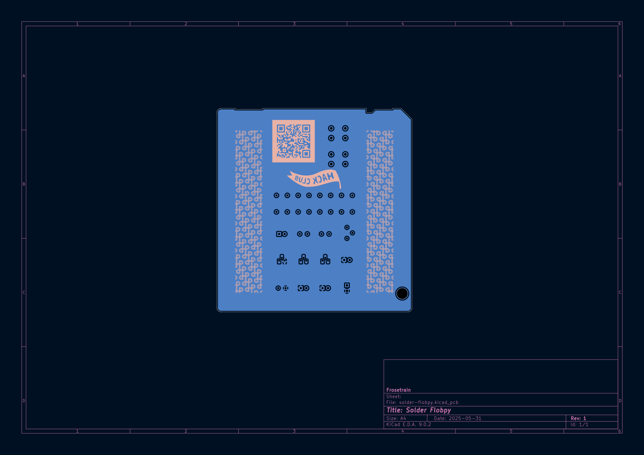
PCB in the exact shape of a floppy disk according to ECMA 147
Solder flobpy is an open-source printed circuit board by frosetrain, from the frosetrain/solder-flobpy repository on GitHub, published under the GPL-3.0 licence. It is a 2-layer board of 90 × 94 mm with 23 parts on 17 nets, routed with 78 tracks and 2 vias.
Its parts include 8 resistors, 4 diodes, 3 transistors, 2 capacitors and 2 switches.
I made a PCB that is the exact shape as a floppy disk, with some interactive components.
Slack username: frosetrain
Made for https://solder.hackclub.com
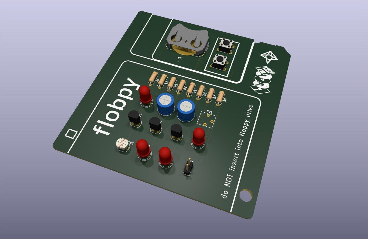
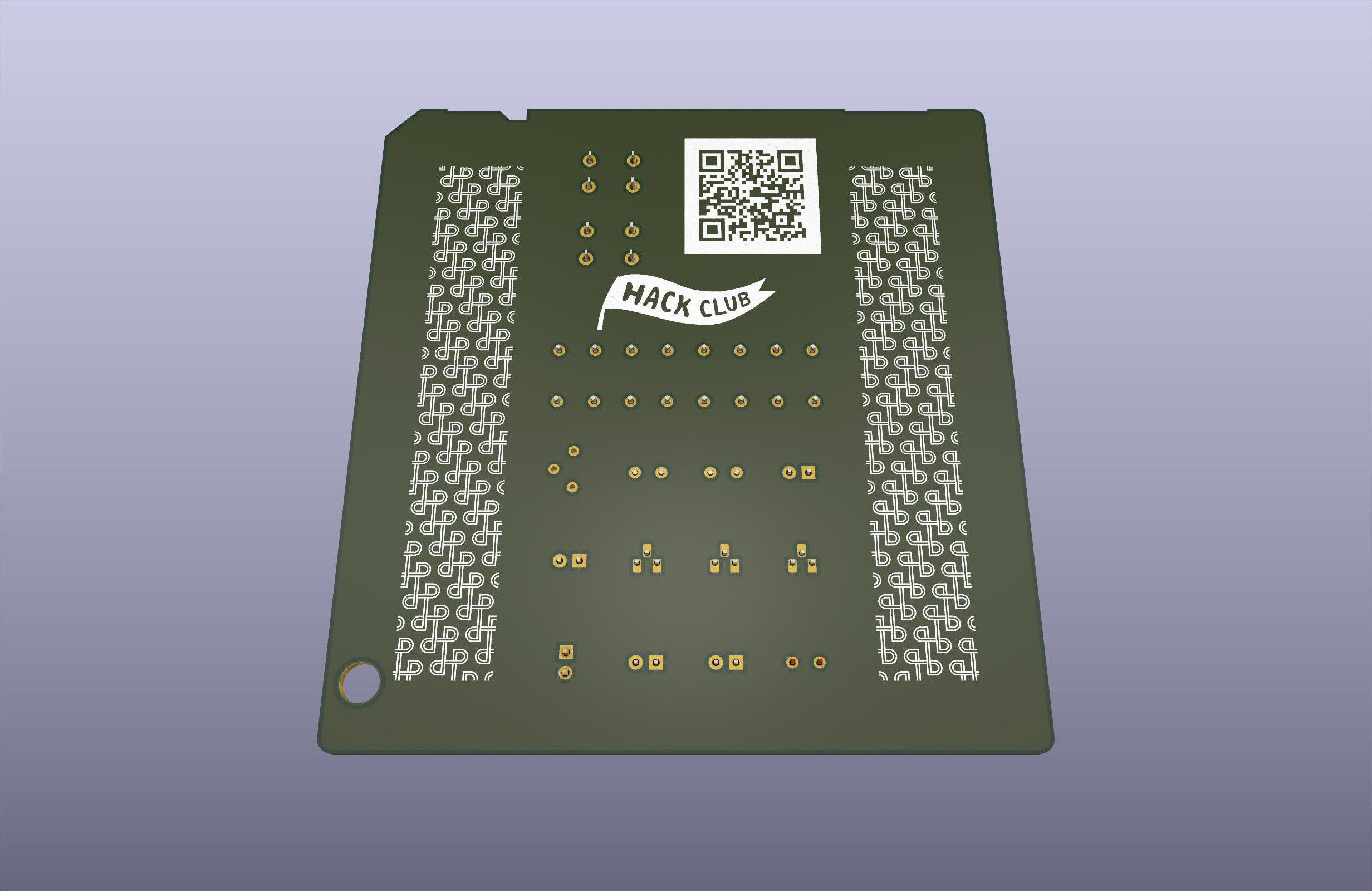
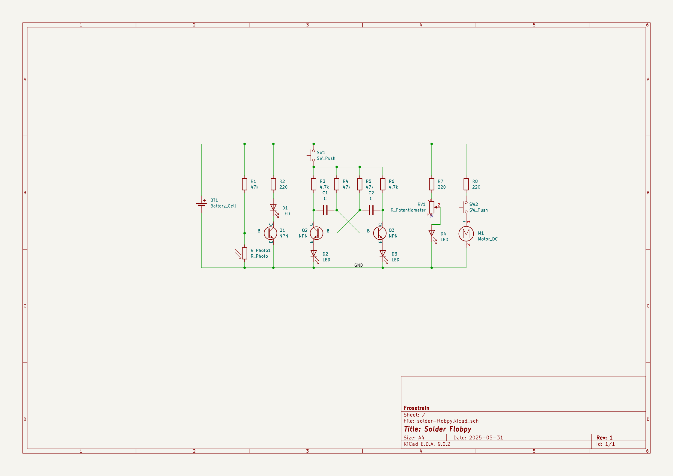
The first LED lights up when the surrounding brightness is below a certain threshold. It uses a photoresistor and NPN transistor.
This uses four resistors, two capacitors and two NPN transistors. This circuit makes the two LEDs flash in an alternating pattern. (I got this circuit idea from Falstad’s Circuit JS)
It’s just a potentiometer.
With the push of a button, the thing vibrates!
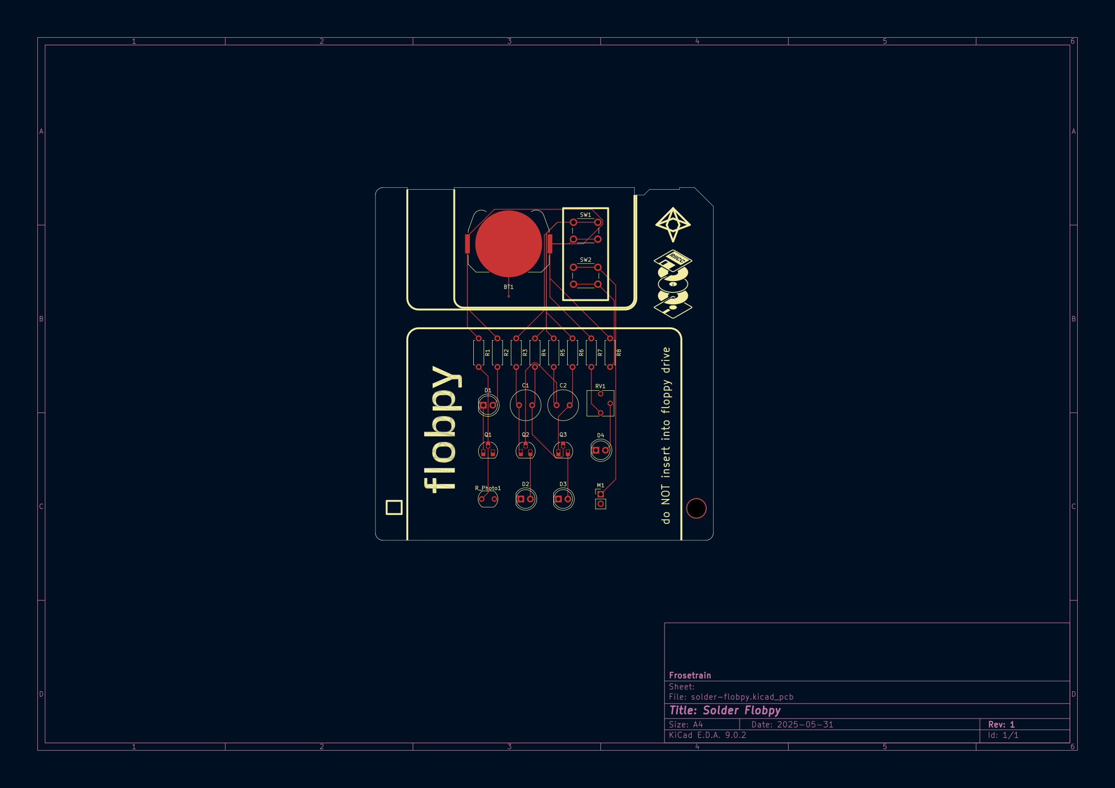
I initially wanted to make a PCB in the shape of a floppy disk. To do this, I needed an accurate vector image of a floppy disk to add to KiCad. I could not find one (everything online was a goofy emoji). So I painstakingly went through ECMA 147, the standard that defines floppy disks, and drew everything exactly in Inkscape.
For the logic, I was unfamiliar with how transistors worked, but thankfully Falstad’s Circuit JS allowed me to learn how it worked, and design my own circuit.
I decided to use a ground fill only on the back side. Maybe it should have been both sides.
I also added some lines to make it look like a floppy disk, and added some other text and images 👍
| Qty | Value | Footprint | References |
|---|---|---|---|
| 4 | LED | LED_THT:LED_D5.0mm | D1, D2, D3, D4 |
| 3 | 220 | Resistor_THT:R_Axial_DIN0207_L6.3mm_D2.5mm_P7.62mm_Horizontal | R2, R7, R8 |
| 3 | 47k | Resistor_THT:R_Axial_DIN0207_L6.3mm_D2.5mm_P7.62mm_Horizontal | R1, R4, R5 |
| 3 | NPN | Package_TO_SOT_THT:TO-92_HandSolder | Q1, Q2, Q3 |
| 2 | 4.7k | Resistor_THT:R_Axial_DIN0207_L6.3mm_D2.5mm_P7.62mm_Horizontal | R3, R6 |
| 2 | C | Capacitor_THT:C_Radial_D8.0mm_H7.0mm_P3.50mm | C1, C2 |
| 2 | SW_Push | Button_Switch_THT:SW_PUSH_6mm | SW1, SW2 |
| 1 | Battery_Cell | Battery:BatteryHolder_Keystone_3034_1x20mm | BT1 |
| 1 | Motor_DC | Connector_PinHeader_2.54mm:PinHeader_1x02_P2.54mm_Vertical | M1 |
| 1 | R_Photo | OptoDevice:R_LDR_5.1x4.3mm_P3.4mm_Vertical | R_Photo1 |
| 1 | R_Potentiometer | Potentiometer_THT:Potentiometer_Vishay_T73YP_Vertical | RV1 |
It measures 90 × 94 mm and has 2 copper layers, 1.6 mm thick.
23 parts. The full list of its parts is on this page, with links to each part's symbol and footprint where PCBKit's library has them.
From the frosetrain/solder-flobpy repository on GitHub, at the commit this page was made from: the board is src/solder-flobpy.kicad_pcb and its schematic src/solder-flobpy.kicad_sch. PCBKit opens the board in the browser, with nothing to install.
Its repository publishes it under the GPL-3.0 licence: you may reuse it on that licence's terms (keep the author's notice, and for a copyleft licence share your changes alike).

google/mozc-devices
Circuit diagrams and firmware source code for Gboard DIY keyboards


Duet3D/Duet-2-Hardware
The KiCAD source for the Duet 3d printer controller see www.duet3d.com