
4 layers234 × 84 mm
Main panel
google/mozc-devices
Circuit diagrams and firmware source code for Gboard DIY keyboards
234 parts3kApache-2.0

 freillyskis-coder/Telemetry-Macropad
This is a place where I store all of my files for my macropad that has an accelerometer, display, and lights that will show telemetry information for racing.
Accelerometer is an open-source printed circuit board by freillyskis-coder, from the freillyskis-coder/Telemetry-Macropad repository on GitHub. It is a 2-layer board of 59.5 × 83.3 mm with 10 parts on 22 nets, routed with 121 tracks and 11 vias.
It is built around the SK6812MINI-E. Its parts include 4 diodes, 3 switches, 2 connectors and 1 IC. It belongs with the sensors and measurement and keyboards and input boards and the RP2040 boards of this library.
This is a place where I store all of my files for my macropad that has an accelerometer, display, and lights that will show telemetry information for racing.
This macropad has a computer, display, accelerometer, a few lights, and 3 keys. The accelerometer is used to measure acceleration in different directions (duh). That information gets used to display which direction it is accelerating in a traction-circle style display, or in plain number format, on the screen. The lights also indicate what direction the board is accelerating, with one pointing in each cardinal direction for the device. The lights each have two functions, requiring a long or short press. They go like this:
I have seen traction circles be used in racing simulators to assist the driver. However, I had never seen one in a real car. I thought it would be really cool to try my hand at designing a device that could display information relevant to racing. In the future, I may add new features such as data collection, slip warnings, etc.
I haven't done that much design work myself, so this was full of new experiences for me. I have used onshape for 3d cad work before, so it was fun learning how to use fusion (they were pretty similar, at least for what I was doing). I also enjoyed learning how to use the KiCAD software. I've used Rapidharness before for electrical work, but it was so cool and different designing a PCB. One of the biggest challenges was the coding, as I've only used Java for my compsci class, and figuring out how to use Github (it required a lot of youtube tutorials and headscratching). Overall, I persisted through and I gained a lot of valuable skills and had a good time!
| Schematic | PCB | Case |
|---|---|---|
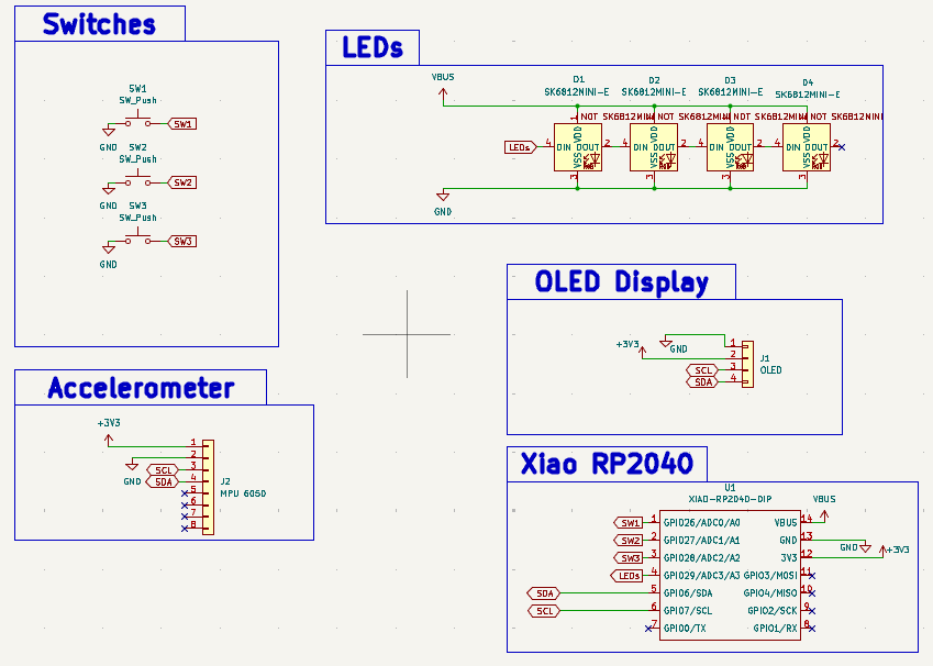 | 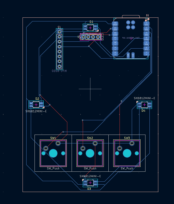 | 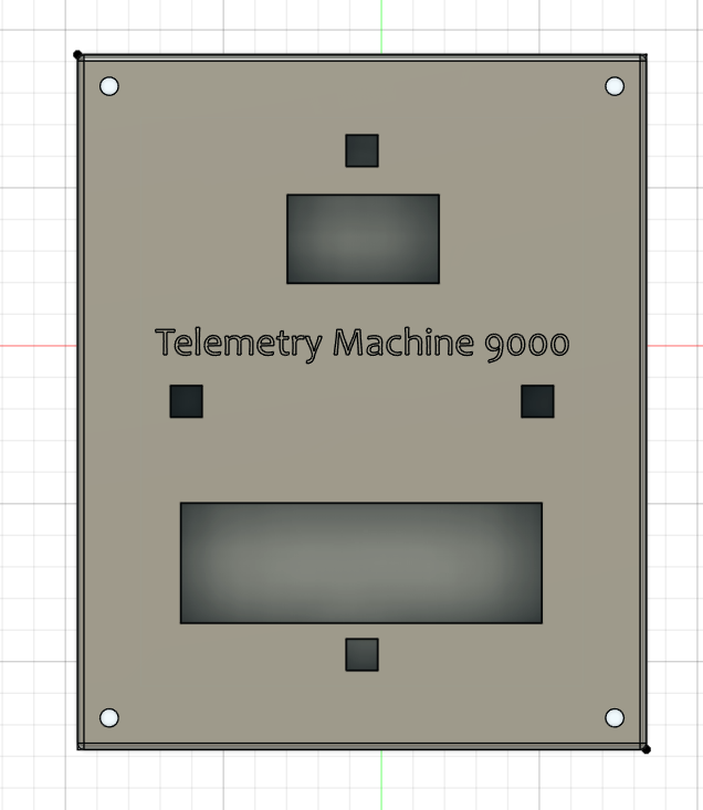 |
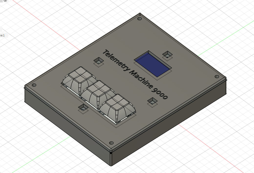
I have an accelerometer and 0.96" display in my designs, but I am not requesting them as I know it they not a part of the kit. I will pay for this myself.
| Qty | Value | Footprint | References |
|---|---|---|---|
| 4 | SK6812MINI-E | SK6812MINI-E:SK6812MINI-E_fixed | D1, D2, D3, D4 |
| 3 | SW_Push | Button_Switch_Keyboard:SW_Cherry_MX_1.00u_PCB | SW1, SW2, SW3 |
| 1 | MPU 6050 | Connector_PinHeader_2.54mm:PinHeader_1x08_P2.54mm_Vertical | J2 |
| 1 | OLED | Connector_PinHeader_2.54mm:PinHeader_1x04_P2.54mm_Vertical | J1 |
| 1 | XIAO-RP2040-DIP | Seeed Studio XIAO Series Library:XIAO-RP2040-SMD | U1 |
It measures 59.5 × 83.3 mm and has 2 copper layers, 1.6 mm thick.
10 parts, built around the SK6812MINI-E. The full list of its parts is on this page, with links to each part's symbol and footprint where PCBKit's library has them.
From the freillyskis-coder/Telemetry-Macropad repository on GitHub, at the commit this page was made from: the board is Telemetry Hackpad/KiCAD Designs/Accelerometer.kicad_pcb and its schematic Telemetry Hackpad/KiCAD Designs/Accelerometer.kicad_sch. PCBKit opens the board in the browser, with nothing to install.
Its repository states no licence, so its author keeps all rights: ask freillyskis-coder before reusing the design.
google/mozc-devices
Circuit diagrams and firmware source code for Gboard DIY keyboards

Bastardkb/Dilemma
The Dilemma is a vertical stagger low-profile keyboard with mods.

Pwnsat/FlatSat
Flatsat v1.0 is a hardware based platform for aerospace cybersecurity research

adamws/kicad-kbplacer
KiCad plugin for automatic keyboard's key placement and routing

imchipwood/dumbpad
Simple 4x4 numpad with rotary encoder. Powered by QMK via ATmega32u4 Pro Micro

makerforgetech/modular-biped
An open source framework for creating a bipedal modular companion robot.

