

4 layers45 × 32 mm
Templog mainboard
Michael-Manning/E-Paper-Climate-Logger
Firmware, PCB, and enclosure for the Weathergotchi E-Paper climate logger.
68 parts457MIT

 FREILab/3DPrinter_Matrix_Display
Matrix Display to display remaining Print Time (Octoprint)
RGB board is an open-source printed circuit board by FREILab, from the FREILab/3DPrinter_Matrix_Display repository on GitHub. It is a 2-layer board of 63.5 × 44.5 mm with 27 parts on 23 nets, routed with 111 tracks and 9 vias.
It is built around the SI1308EDL and CDBC540-G. Its parts include 8 resistors, 5 capacitors, 3 transistors, 3 connectors and 1 IC. It belongs with the lEDs and displays boards of this library.
This is a hardware / software project to display the remianing print time for the FREILab printers
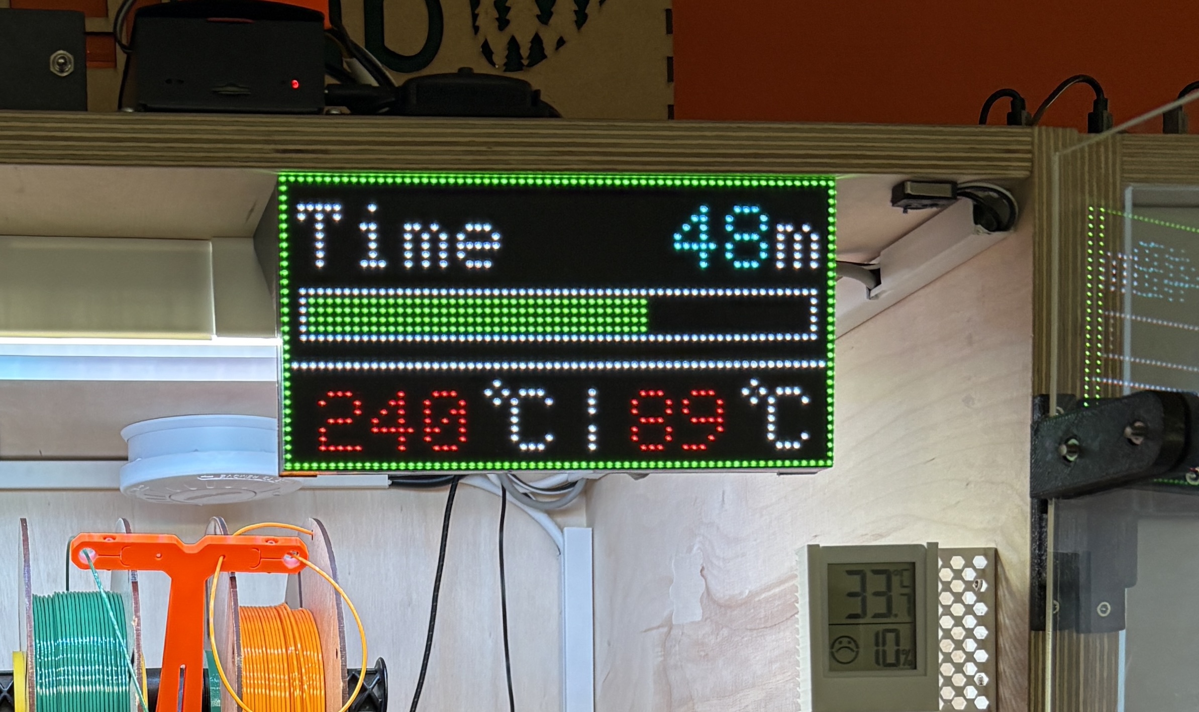
The Display is powered by to the Raspberry Pi which controls the 3D Printer via Octoprint. The Adafruit MCU Board MatrixPortal S3 connects via its built in WiFi card to the Octoprint Instance and displays the current hotend and bed temperature as well as the print job progress and remaining time on the matrix display.
The following hardware is used:
The display uses these significant libraries:
The were some issues with the Octoprint API which locked up the MCU when a print job was started/finished. Instead of fixing the API itself, a simple watchdog was implemented to restart the Adafruit MatrixPortal S3 when the software freezes.
| Qty | Value | Footprint | References |
|---|---|---|---|
| 4 | 10k | Resistor_SMD:R_0805_2012Metric | R2, R4, R6, R8 |
| 3 | 100R | Resistor_SMD:R_0805_2012Metric | R1, R3, R5 |
| 3 | Si1308EDL | Package_TO_SOT_SMD:SOT-323_SC-70 | Q1, Q2, Q3 |
| 2 | 10uF | Capacitor_SMD:C_0805_2012Metric | C1, C2 |
| 2 | 22uF | Capacitor_SMD:C_0805_2012Metric | C4, C5 |
| 2 | Conn_01x04 | aa_MyParts:T_4_PhoenixContact_LPT_5_4-H-1x04_Horizontal | J2, J3 |
| 1 | S3_MATRIXPORTAL_BOT | U$26 | |
| 1 | S3_MATRIXPORTAL_TOP | U$25 | |
| 1 | +5V_Screw | MountingHole:MountingHole_3.2mm_M3_Pad_TopBottom | H1 |
| 1 | 100nF | Capacitor_SMD:C_0805_2012Metric | C3 |
| 1 | 3.3uH, 6A | Inductor_SMD:L_Bourns_SRP7028A_7.3x6.6mm | L1 |
| 1 | 56k2 | Resistor_SMD:R_0805_2012Metric | R7 |
| 1 | CDBC540-G | Diode_SMD:D_SMC | D1 |
| 1 | Conn_01x11 | aa_MyParts:J_FM11x2_2.5476341-311LF | J1 |
| 1 | GND_Screw | MountingHole:MountingHole_3.2mm_M3_Pad_TopBottom | H2 |
| 1 | LOGO | Library:FeiLab_Logo | G*** |
| 1 | TPS563200 | Package_TO_SOT_SMD:SOT-23-6 | U1 |
It measures 63.5 × 44.5 mm and has 2 copper layers, 1.6 mm thick.
27 parts, built around the SI1308EDL and CDBC540-G. The full list of its parts is on this page, with links to each part's symbol and footprint where PCBKit's library has them.
From the FREILab/3DPrinter_Matrix_Display repository on GitHub, at the commit this page was made from: the board is Hardware/RGB_board/RGB_board.kicad_pcb and its schematic Hardware/RGB_board/RGB_board.kicad_sch. PCBKit opens the board in the browser, with nothing to install.
Its repository states no licence, so its author keeps all rights: ask FREILab before reusing the design.
Michael-Manning/E-Paper-Climate-Logger
Firmware, PCB, and enclosure for the Weathergotchi E-Paper climate logger.


gab-k/RP2040-Decoder
Cost effective DIY DCC Decoder for model railroad locomotives

EnriqueNeyra/Aeroq
An Indoor Air Quality Monitor Powered by ESP32, SCD40, and SEN54

EnriqueNeyra/aether
All-in-one home air quality monitor measuring Temp, Humidity, CO2, VOCs, Particulate Matter, and NOx. Powered by ESP32-C3 running esphome, and built with Home Assistant integration


solderable/storm-tracker-hardware
Open-source-ready Storm Tracker hardware design, documentation, BOM, and manufacturing package

martinberlin/bistable-smart-switch
An epaper switch project with 2 PCBs, controller+touch, and 220AC to 3DC with Relay (Latch or solid-state)