4 layers50 × 80 mm
SensBoard
Hazel-H-Chen/PocketSens
Microcontroller based sensor suite for portable environmental measurements.
62 parts1MIT

 solderable/storm-tracker-hardware58
Open-source-ready Storm Tracker hardware design, documentation, BOM, and manufacturing package
Storm tracker is an open-source printed circuit board by solderable, from the solderable/storm-tracker-hardware repository on GitHub. It is a 4-layer board of 36.5 × 69 mm with 102 parts on 66 nets, routed with 485 tracks and 342 vias.
It is built around the ESP32-C6-MINI-1U-H4, AS3935-BQFT and SHT40-AD1B-R2, with the BQ25186DLHR, TLV75533PDBVR-MS and USBLC6-2P6 among its other parts. Its parts include 31 capacitors, 20 resistors, 8 diodes, 6 ICs and 5 switches. It belongs with the ESP32 and RISC-V boards of this library.


Storm Tracker is a pocket-sized, battery-powered lightning detector. It uses a 500 kHz magnetic-loop antenna and a ScioSense AS3935 to detect lightning-like radio bursts, estimates the distance to the storm front, and presents status on a sunlight-readable e-paper display.
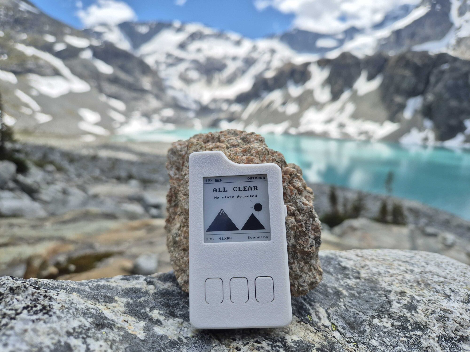
A working Storm Tracker prototype in the field. Photo from the project story.
[!CAUTION] Storm Tracker is experimental hobby hardware, not certified weather or life-safety equipment. It can miss lightning and can report false positives. Never use it instead of official forecasts, alerts, or safe lightning practices.
Rev A complete / fabrication-ready. Rev A boards have been fabricated, assembled, brought up, carried in the field, and have detected a real storm. The released KiCad design passes both ERC and DRC with zero violations. This repository contains the complete editable PCB design, ordering package, BOM, assembly guidance, and no-CAD-needed reference exports for the hardware revision shown in the photographs.
| Area | Status | Where to start |
|---|---|---|
| Editable PCB design | Complete; KiCad 10 | hardware/ |
| Schematic and board PDFs | Complete | docs/reference/ |
| Complete electronics BOM | Complete | bom/storm-tracker-full.csv |
| JLCPCB-ready Rev A outputs | Complete; standard 4-layer stack | manufacturing/rev-a/ |
| Design explanation | Complete | Why the design looks this way |
| Assembly and bring-up | Complete | Build one |
| Electrical checks | ERC 0 / DRC 0 | KiCad 10 |
| Item | Rev A |
|---|---|
| PCB outline | 36.5 × 69.0 mm, plus internal display slot |
| PCB construction | 4 layers, nominal 1.0 mm FR-4 |
| Lightning sensor | ScioSense AS3935-BQFT |
| Antenna | Coilcraft MA5532-AED, tuned near 500 kHz |
| MCU | ESP32-C6-MINI-1U-H4 |
| Display | Good Display GDEY0154D67, 1.54 in, 200 × 200 e-paper |
| Power | Single-cell LiPo, USB-C charging, BQ25186 Ship Mode |
| User input | Three front buttons and one side power button |
| Alerts | E-paper status and magnetic buzzer |
| Idle design budget | About 98 µA |
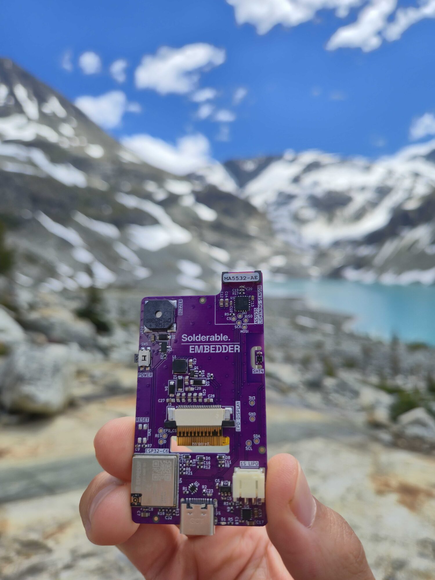
|
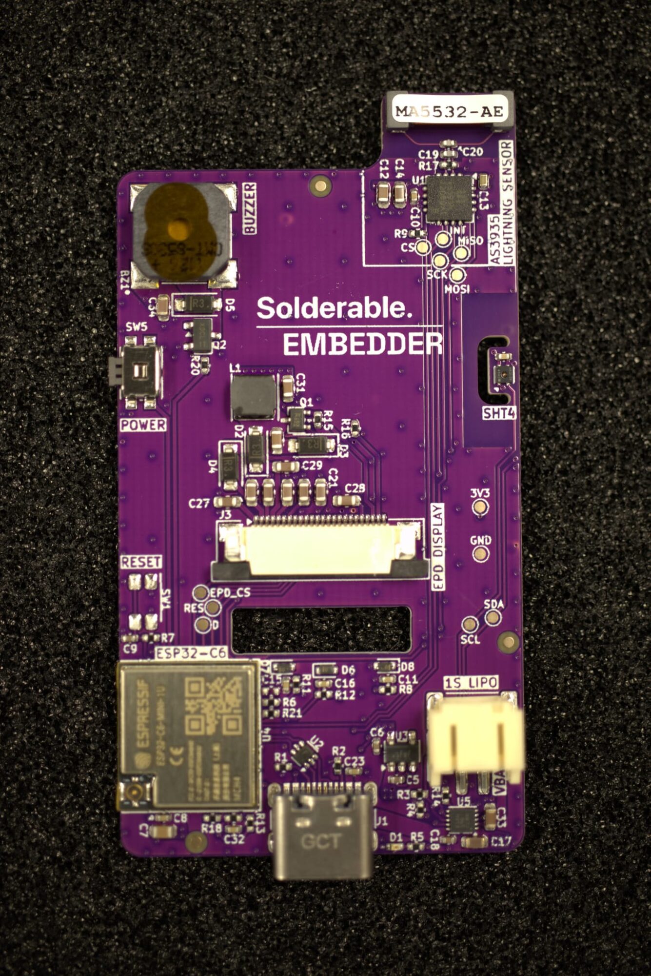
|
| Assembled Rev A PCB in the field | Populated component side |
These are photographs of the fabricated Rev A hardware documented in this repository. More build and field-test photos are in the project story.
storm-tracker-hardware/
├── hardware/                 KiCad 10 source and required local libraries
├── bom/                      Complete-build CSV BOM
├── manufacturing/rev-a/      Gerber ZIP, position data, and order settings
├── mechanical/               PCB assembly STEP model
└── docs/
    ├── images/               Three prototype photographs
└── reference/ Schematic and board-layer PDFshardware/storm_tracker.kicad_pro.If you do not use KiCad, start with the schematic PDF, the board layer PDF, and the complete BOM.
Use the order-ready files and settings in the Rev A manufacturing package. For JLCPCB, select the standard four-layer, nominal 1.0 mm FR-4 construction with 1 oz outer copper, 0.5 oz inner copper, and No requirement for the stackup. This is JLCPCB's standard 7628 / 0.5 mm core construction and matches the stack encoded in the KiCad board.
Most electrical components are on the bottom side so a factory can populate one face. SW1 (reset) and JP1 (boot) are DNP in Rev A. Suggested sequence:
The display cable folds through the board into a reverse-pin-numbered local footprint. Never insert, remove, or reseat it with USB or battery power present. Round the PCB slot edge and provide strain relief so the flex is not cut by the board.
The AS3935 listens around 500 kHz, so switching noise can look like a storm. Rev A therefore uses an LDO for the always-on 3.3 V rail, keeps the magnetic loop on a copper-free peninsula, and only runs the e-paper boost converter during screen refreshes. Firmware must put the lightning sensor to sleep while the display boost is active.
The project story covers the build narrative and the reasoning behind these choices in more detail.
Beyond the lightning caveat above:
Hardware design: Isaak Devos / Solderable. Prototype firmware and bring-up: Embedder collaboration.
| Qty | Value | Footprint | References |
|---|---|---|---|
| 9 | 10k | Resistor_SMD:R_0402_1005Metric | R6, R7, R8, R9, R11, R12, R13, R14, R21 |
| 9 | 1uF 25V | Capacitor_SMD:C_0603_1608Metric | C14, C21, C22, C24, C25, C26, C27, C28, C29 |
| 8 | 100nF | Capacitor_SMD:C_0402_1005Metric | C1, C8, C10, C11, C15, C16, C23, C32 |
| 4 | 1uF | Capacitor_SMD:C_0402_1005Metric | C5, C6, C9, C18 |
| 4 | LOGO | LOGO | G***, G***, G***, G*** |
| 4 | MBR0530 | Diode_SMD:D_SOD-123 | D2, D3, D4, D5 |
| 3 | 10uF | Capacitor_SMD:C_0603_1608Metric | C17, C33, C34 |
| 3 | 1M | Resistor_SMD:R_0402_1005Metric | R16, R18, R19 |
| 3 | ESD5Z3.3T1G | Diode_SMD:D_SOD-523 | D6, D7, D8 |
| 2 | 4.7uF 25V | Capacitor_SMD:C_0603_1608Metric | C30, C31 |
| 2 | 4k7 | Resistor_SMD:R_0402_1005Metric | R3, R4 |
| 2 | 5k1 | Resistor_SMD:R_0402_1005Metric | R1, R2 |
| 1 | 100 | Resistor_SMD:R_0402_1005Metric | R20 |
| 1 | 10k 1% | Resistor_SMD:R_0402_1005Metric | R17 |
| 1 | 10uF | Capacitor_SMD:C_0402_1005Metric | C13 |
| 1 | 2.2R | Resistor_SMD:R_0402_1005Metric | R15 |
| 1 | 22uF | Capacitor_SMD:C_0603_1608Metric | C7 |
| 1 | 270pF C0G | Capacitor_SMD:C_0402_1005Metric | C20 |
| 1 | 3V3 | TestPoint:TestPoint_Pad_D1.0mm | TP4 |
| 1 | 4.7uF | Capacitor_SMD:C_0603_1608Metric | C12 |
| 1 | 47uH 0.5A | Inductor_SMD:L_APV_ANR4030 | L1 |
| 1 | 680 | Resistor_SMD:R_0402_1005Metric | R5 |
| 1 | 680pF C0G | Capacitor_SMD:C_0402_1005Metric | C19 |
| 1 | AO3400A | Package_TO_SOT_SMD:SOT-23 | Q2 |
| 1 | AS3935 | Package_DFN_QFN:MLPQ-16-1EP_4x4mm_P0.65mm_EP2.8x2.8mm | U1 |
| 1 | AS_CS | TestPoint:TestPoint_Pad_D1.0mm | TP12 |
| 1 | AS_INT | TestPoint:TestPoint_Pad_D1.0mm | TP17 |
| 1 | BQ25186DLHR | Package_DFN_QFN:Texas_DLH0010A_WSON-10-1EP_2.2x2mm_P0.4mm_EP0.9x1.5mm_ThermalVias | U5 |
| 1 | BTN_LEFT | Button_Switch_SMD:SW_SPST_SKQG_WithStem | SW2 |
| 1 | BTN_MODE | Button_Switch_SMD:SW_SPST_SKQG_WithStem | SW4 |
| 1 | BTN_RIGHT | Button_Switch_SMD:SW_SPST_SKQG_WithStem | SW3 |
| 1 | Batt | Connector_JST:JST_PH_S2B-PH-SM4-TB_1x02-1MP_P2.00mm_Horizontal | J2 |
| 1 | CMT-8530S | Library:CUI_CMT-8530S-SMT | BZ1 |
| 1 | D | TestPoint:TestPoint_Pad_D1.0mm | TP15 |
| 1 | Display_GDEY0154D67_Mech | Library:Display_GDEY0154D67_Mech | DISP_REF |
| 1 | EPD_CS | TestPoint:TestPoint_Pad_D1.0mm | TP13 |
| 1 | ESP32-C6-MINI-1 | Library:ESP32-C6-MINI-1U | U4 |
| 1 | FPC_24_Epaper_SSD1680 | Library:Amphenol_F32Q-1A7x1-11024_1x24-1MP_P0.5mm_Horizontal_RevPinout | J3 |
| 1 | GND | TestPoint:TestPoint_Pad_D1.0mm | TP3 |
| 1 | MA5532-AE | RF_Antenna:Coilcraft_MA5532-AE_RFID | L2 |
| 1 | MISO | TestPoint:TestPoint_Pad_D1.0mm | TP9 |
| 1 | MOSI | TestPoint:TestPoint_Pad_D1.0mm | TP11 |
| 1 | PWR_BTN | Button_Switch_SMD:Panasonic_EVQPUM_EVQPUD | SW5 |
| 1 | RES | TestPoint:TestPoint_Pad_D1.0mm | TP14 |
| 1 | RST_BTN | Button_Switch_SMD:SW_SPST_EVQP7A | SW1 |
| 1 | Red Led | LED_SMD:LED_0402_1005Metric | D1 |
| 1 | SCK | TestPoint:TestPoint_Pad_D1.0mm | TP10 |
| 1 | SCL | TestPoint:TestPoint_Pad_D1.0mm | TP6 |
| 1 | SDA | TestPoint:TestPoint_Pad_D1.0mm | TP7 |
| 1 | SHT40-AD1B-R2 | Sensor_Humidity:Sensirion_DFN-4_1.5x1.5mm_P0.8mm_SHT4x_NoCentralPad | U6 |
| 1 | Si1308EDL | Package_TO_SOT_SMD:SOT-323_SC-70 | Q1 |
| 1 | TLV75533PDBV | Package_TO_SOT_SMD:SOT-23-5 | U3 |
| 1 | USBLC6-2P6 | Package_TO_SOT_SMD:SOT-666 | U2 |
| 1 | USB_C_Receptacle_USB2.0_16P | Connector_USB:USB_C_Receptacle_GCT_USB4105-xx-A_16P_TopMnt_Horizontal | J1 |
| 1 | boot | Resistor_SMD:R_0402_1005Metric | JP1 |
The 96 most common of 102 parts.
It measures 36.5 × 69 mm and has 4 copper layers, 1.04 mm thick.
102 parts, built around the ESP32-C6-MINI-1U-H4, AS3935-BQFT, SHT40-AD1B-R2 and BQ25186DLHR. The full list of its parts is on this page, with links to each part's symbol and footprint where PCBKit's library has them.
From the solderable/storm-tracker-hardware repository on GitHub, at the commit this page was made from: the board is hardware/storm_tracker.kicad_pcb and its schematic hardware/storm_tracker.kicad_sch. PCBKit opens the board in the browser, with nothing to install.
Its repository states no licence, so its author keeps all rights: ask solderable before reusing the design.
Hazel-H-Chen/PocketSens
Microcontroller based sensor suite for portable environmental measurements.


nischayhegde/jetson_spi_to_can_x8_breakout
A PCB board for expanding the SPI channels on Jetson Orin nano super into 8 CANfd channels. Comes with chip select logic and jetpack drivers. Supports 1Mbit per CAN channel.

tmpk13/cc1200-balloon
High altitude balloon payload: a CC1200 sub-GHz telemetry downlink and an air quality sensor stack, hosted by a Seeed Wio-E5 module. Four-layer 50 x 30 mm board, routed.

vbartusevicius/weather-station
Open-source rooftop weather and air-quality station with no moving parts (Ø 96 × 235 mm, UV-stabilised ASA): ultrasonic wind, acoustic rain and hail, UV / sunlight / night-sky brightness, temperature, humidity…