
2 layers160 × 124.7 mm

Electrical design repository for the FS-2 racecar
BMS is an open-source printed circuit board by formulaslug, from the formulaslug/fs-2-schematics repository on GitHub. It is a 2-layer board of 59.4 × 76.8 mm with 97 parts on 95 nets, routed with 581 tracks and 34 vias.
It is built around the ADG708BRU, LTC6811IG-1 and BSS308PE, with the HM2113ZNLT and NSV1C201MZ4 among its other parts. Its parts include 45 resistors, 14 capacitors, 9 diodes, 8 transistors and 8 fuses. It belongs with the power boards of this library.



This is the electrical schematics repository for the FS-2 racecar.
Report Bug
·
Request Feature
In depth version of how to get started 🏎️
If you installed GitHub desktop, create an account and close the repository. I recommend cloning the repository into your documents folder.
How to clone repositories on GitHub desktop
The repository url is: https://github.com/formulaslug/fs-2-schematics
If you are tech savvy and using Git
$ git clone https://github.com/formulaslug/fs-2-schematics
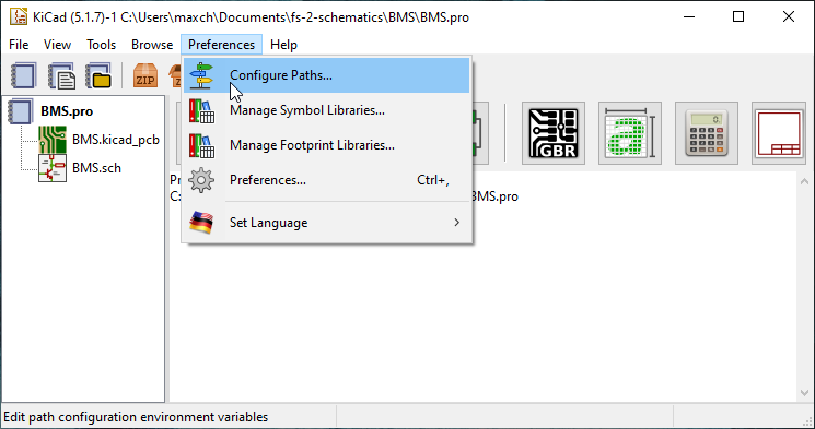
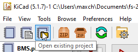
Make sure KiCAD is currently open
Then click on preferences -> Configure Paths..
Click on the plus on the bottom right to add a new path variable
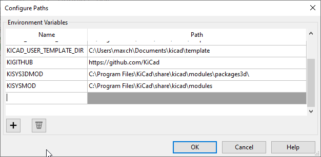
On the left, you want it FS_2_SCHEMATICS <- all caps
On the right, you want to set the path where you installed the repository (the folder is called fs-2-schematics)

Click on the folder on the right, and find fs-2-schematics repo like stated above
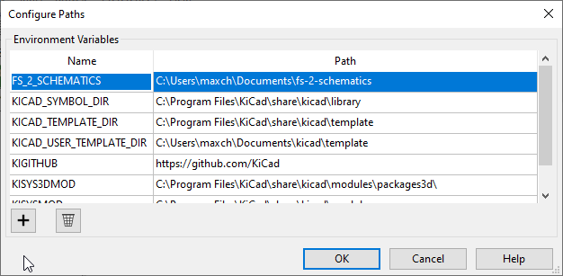
Should look something like this after its done
Example (might look different if you are using an Mac, or Linux):
| Left side | Right side |
|---|---|
| FS_2_SCHEMATICS | Docs\fs-2-schematics |
This is the design for the LTC6811-based BMS module, based on the design from fs-1.
| Qty | Value | Footprint | References |
|---|---|---|---|
| 9 | 100 | Resistor_SMD:R_0805_2012Metric_Pad1.15x1.40mm_HandSolder | R1, R2, R14, R18, R22, R26, R30, R36, R45 |
| 9 | 10nF | Capacitor_SMD:C_0805_2012Metric_Pad1.15x1.40mm_HandSolder | C2, C4, C5, C8, C9, C10, C11, C13, C14 |
| 8 | Polyfuse | Fuse:Fuse_1812_4532Metric_Pad1.30x3.40mm_HandSolder | F1, F2, F3, F4, F5, F6, F7, F8 |
| 7 | 120 | Resistor_SMD:R_0805_2012Metric_Pad1.15x1.40mm_HandSolder | R9, R15, R19, R23, R27, R31, R42 |
| 7 | 3.3k | Resistor_SMD:R_0805_2012Metric_Pad1.15x1.40mm_HandSolder | R11, R17, R21, R25, R29, R35, R44 |
| 7 | 33 | Capacitor_SMD:C_2512_6332Metric_Pad1.52x3.35mm_HandSolder | R10, R16, R20, R24, R28, R34, R43 |
| 7 | BSS308PE | Package_TO_SOT_SMD:SOT-23 | Q2, Q3, Q4, Q5, Q6, Q7, Q8 |
| 7 | LH R974-LP-1 | Diode_SMD:D_0805_2012Metric_Pad1.15x1.40mm_HandSolder | D2, D3, D4, D5, D6, D7, D8 |
| 5 | 10k | Resistor_SMD:R_0805_2012Metric_Pad1.15x1.40mm_HandSolder | R7, R8, R37, R38, R39 |
| 4 | MountingHole_3.2mm_M3 | MountingHole:MountingHole_3.2mm_M3 | , , , |
| 3 | 1uF | Capacitor_SMD:C_0805_2012Metric_Pad1.15x1.40mm_HandSolder | C3, C6, C7 |
| 2 | 160 | Resistor_SMD:R_0805_2012Metric_Pad1.15x1.40mm_HandSolder | R6, R51 |
| 2 | 22 | Resistor_SMD:R_0805_2012Metric_Pad1.15x1.40mm_HandSolder | R40, R41 |
| 2 | IsoSPI | Connector_Molex:Molex_Nano-Fit_105313-xx02_1x02_P2.50mm_Horizontal | J3, J4 |
| 2 | LH R974-LP-1 | LED_SMD:LED_0805_2012Metric_Pad1.15x1.40mm_HandSolder | D1, D9 |
| 1 | 1.5k | Resistor_SMD:R_0805_2012Metric_Pad1.15x1.40mm_HandSolder | R12 |
| 1 | 100 | Capacitor_SMD:C_0805_2012Metric_Pad1.15x1.40mm_HandSolder | R3 |
| 1 | 100nF | Capacitor_SMD:C_0805_2012Metric_Pad1.15x1.40mm_HandSolder | C1 |
| 1 | 15pF | Capacitor_SMD:C_0805_2012Metric_Pad1.15x1.40mm_HandSolder | C12 |
| 1 | 2.2k | Resistor_SMD:R_0805_2012Metric_Pad1.15x1.40mm_HandSolder | R33 |
| 1 | 200 | Resistor_SMD:R_0805_2012Metric_Pad1.15x1.40mm_HandSolder | R5 |
| 1 | 402 | Resistor_SMD:R_0805_2012Metric_Pad1.15x1.40mm_HandSolder | R32 |
| 1 | 680 | Resistor_SMD:R_0805_2012Metric_Pad1.15x1.40mm_HandSolder | R13 |
| 1 | ADG708 | Package_SO:TSSOP-16_4.4x5mm_P0.65mm | U2 |
| 1 | Cell Taps | Connector_Molex:Molex_Nano-Fit_105313-xx08_1x08_P2.50mm_Horizontal | J1 |
| 1 | HM2113ZNL | FSFootprints:HM2113ZNL | L1 |
| 1 | LOGO | FSFootprints:fs_logo_full_2400 | G*** |
| 1 | LTC6811 | FSFootprints:FSOP-48_[LTC6811-2] | U1 |
| 1 | NSV1C201MZ4 | Package_TO_SOT_SMD:SOT-223 | Q1 |
| 1 | SW_DIP_x04 | FSFootprints:DIP A6H-4101 | SW1 |
| 1 | Temp Sensors | Connector_Molex:Molex_Nano-Fit_105314-xx14_2x07_P2.50mm_Horizontal | J2 |


formulaslug/fs-2-schematics
Electrical design repository for the FS-2 racecar


formulaslug/fs-2-schematics
Electrical design repository for the FS-2 racecar


formulaslug/fs-2-schematics
Electrical design repository for the FS-2 racecar

formulaslug/fs-2-schematics
Electrical design repository for the FS-2 racecar


corbosiny/SolarCar
All code relating to solar car like: BPS, telemetry, web dev, and more.

Team-Swinburne/ts_20-pcb-development
This is the official repository for the PCB development of Team Swinburne FSAE 2020

Team-Swinburne/ts_23_Altium_Projects
Repository for all the custom PCBs on ts_23


It measures 59.4 × 76.8 mm and has 2 copper layers, 1.6 mm thick.
97 parts, built around the ADG708BRU, LTC6811IG-1, BSS308PE and HM2113ZNLT. The full list of its parts is on this page, with links to each part's symbol and footprint where PCBKit's library has them.
From the formulaslug/fs-2-schematics repository on GitHub, at the commit this page was made from: the board is BMS/BMS.kicad_pcb. PCBKit opens the board in the browser, with nothing to install.
Its repository states no licence, so its author keeps all rights: ask formulaslug before reusing the design.