4 layers162 × 115 mm
Fome mc
halbritt/fome-mc
FOME-MC integrated single-PCB motorcycle ECU (STM32H753 + 2x STM32F042 WBO)
514 parts1
 FOME-Tech/Polygonus21
Polygonus - Brain board for FOME ecus
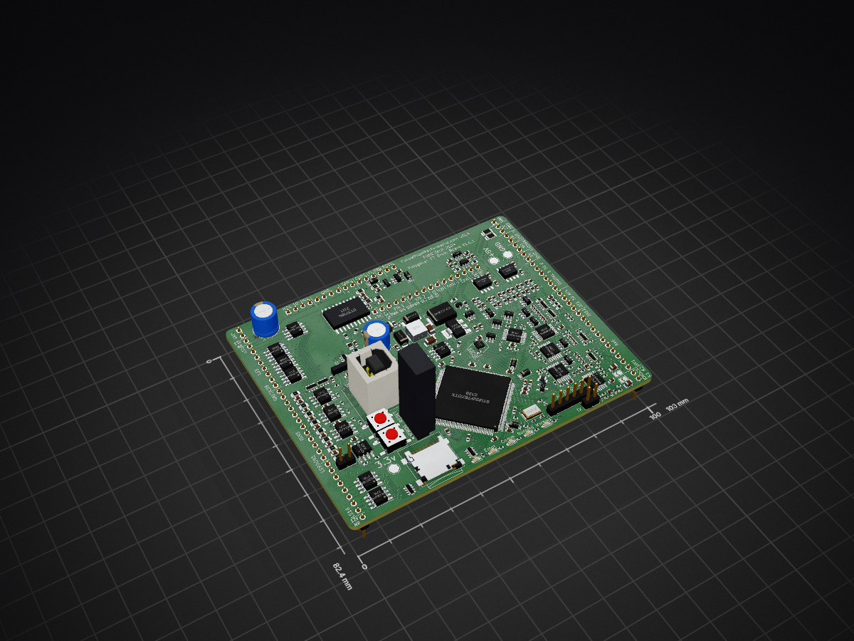
Polygonus Shortage Version is an open-source printed circuit board by FOME-Tech, from the FOME-Tech/Polygonus repository on GitHub. It is a 4-layer board of 103 × 82.4 mm with 319 parts on 328 nets, routed with 2,888 tracks and 887 vias.
It is built around the SN74LVC2G17DBV, MCP2551-I/SN-HG and MCP6004-E/P, with the MIC4427ZM, LPS25HB and VNLD5090TR-E among its other parts. Its parts include 123 resistors, 102 capacitors, 32 ICs, 24 diodes and 16 connectors. It belongs with the STM32 boards of this library.


This is an ECU "brain module". Combined with a "base board", it forms a functional engine control unit compatible with FOME firmware. It is not intended to run an engine without being mated to a base board.
This module is a derivative of the Proteus ECU: for the most part, it is a Proteus with the AMPSEAL connectors replaced with 0.1" headers. It is 100% firmware compatible with Proteus, and indeed uses the Proteus FOME firmware build.
Some early units use STM32F429ZG, this makes little functional difference.
Lowside:
| Pin | Signal | Type |
|---|---|---|
| 1 | Ground | |
| 2 | Ground | |
| 3 | 12V_MR | 12v supplied from main relay. Supplies high side outputs. |
| 4 | LS1 | Lowside output |
| 5 | LS2 | Lowside output |
| 6 | LS3 | Lowside output |
| 7 | LS4 | Lowside output |
| 8 | LS5 | Lowside output |
| 9 | LS6 | Lowside output |
| 10 | LS7 | Lowside output |
| 11 | LS8 | Lowside output |
| 12 | IGN12 | Passthrough to MCU |
| 13 | IGN11 | Passthrough to MCU |
| 14 | IGN10 | Passthrough to MCU |
| 15 | IGN9 | Passthrough to MCU |
| 16 | IGN8 | 5v push-pull output |
| 17 | IGN7 | 5v push-pull output |
| 18 | IGN6 | 5v push-pull output |
| 19 | IGN5 | 5v push-pull output |
| 20 | IGN4 | 5v push-pull output |
| 21 | IGN3 | 5v push-pull output |
| 22 | IGN2 | 5v push-pull output |
| 23 | IGN1 | 5v push-pull output |
| 24 | LS9 | Passthrough to MCU |
| 25 | LS10 | Passthrough to MCU |
| 26 | LS11 | Passthrough to MCU |
| 27 | LS12 | Passthrough to MCU |
| 28 | LS13 | Lowside output |
| 29 | LS14 | Lowside output |
| 30 | LS15 | Lowside output |
| 31 | LS16 | Lowside output |
| 32 | 12V_MR | See pin 3 |
| 33 | Ground | |
| 34 | 12V_PROT | Protected 12v output supplied from 12V_IGN |
| 35 | 12V_PROT | See pin 34 |
| 36 | 5V_SENSOR_2 | 5v sensor supply |
| 37 | 5V_SENSOR_2 | 5v sensor supply |
| 38 | Reserved | |
| 39 | Reserved | |
| 40 | 5V_SENSOR_1 | 5v sensor supply |
| 41 | 5V_SENSOR_1 | 5v sensor supply |
| 42 | DIGITAL_6 | Digital input |
| 43 | DIGITAL_5 | Digital input |
| 44 | DIGITAL_4 | Digital input |
| 45 | DIGITAL_3 | Digital input |
| 46 | DIGITAL_2 | Digital input |
| 47 | DIGITAL_1 | Digital input |
| 48 | AT4 | Analog temp input |
| 49 | AT3 | Analog temp input |
| 50 | AT2 | Analog temp input |
| 51 | AT1 | Analog temp input |
| 52 | AV11 | Analog voltage input |
| 53 | AV10 | Analog voltage input |
| 54 | AV9 | Analog voltage input |
| 55 | AV8 | Analog voltage input |
| 56 | AV7 | Analog voltage input |
| 57 | AV6 | Analog voltage input |
| 58 | AV5 | Analog voltage input |
| 59 | AV4 | Analog voltage input |
| 60 | AV3 | Analog voltage input |
| 61 | AV2 | Analog voltage input |
| 62 | AV1 | Analog voltage input |
| 63 | Knock 1 | Knock sense input |
| 64 | Knock 2 | Knock sense input |
| 65 | HS1 | High side output |
| 66 | HS2 | High side output |
| 67 | HS3 | High side output |
| 68 | HS4 | High side output |
| 69 | Ground | |
| 70 | Ground | |
| 71 | Ground | |
| 72 | Ground | |
| 73 | CAN2+ | CAN bus 2 |
| 74 | CAN2− | CAN bus 2 |
| 75 | RC1 | |
| 76 | RC2 | |
| 77 | Perm_Live | Permanent 12v supply for backup memory supply |
| 78 | Scope | |
| 79 | Reserved | |
| 80 | Reserved | |
| 81 | +5V | 5v power output for base board (250mA max) |
| 82 | +3.3V | 3.3v power output for base board (100mA max) |
| 83 | ETB1_PWM | |
| 84 | ETB1_DIS | |
| 85 | ETB1_DIR | |
| 86 | ETB2_PWM | |
| 87 | ETB2_DIS | |
| 88 | ETB2_DIR | |
| 89 | Ground | |
| 90 | 12V_IGN | Switched ignition switch power. 6-24 volts, reverse polarity protected. |
| 91 | Ground | |
| 92 | Ground | |
| 93 | CAN+ | CAN bus 1 |
| 94 | CAN− | CAN bus 1 |
| 95 | VR2+ | Digital input |
| 96 | VR1+ | Digital input |
| 97 | USB_SHIELD | USB shield |
| 98 | USB_GND | USB ground |
| 99 | USB+ | USB data D+ |
| 100 | USB− | USB data D- |
| 101 | USB_VBUS | USB VBUS input |
| 102 | +3V3 | 3.3v power output for base board (100mA max) |
| 103 | EXT_SPI_CS | SPI bus for base board |
| 104 | EXT_SPI_SCK | SPI bus for base board |
| 105 | EXT_SPI_MISO | SPI bus for base board |
| 106 | EXT_SPI_MOSI | SPI bus for base board |
| 107 | Ground |
| Qty | Value | Footprint | References |
|---|---|---|---|
| 24 | 100n | Capacitor_SMD:C_0603_1608Metric | C10, C40, C41, C46, C51, C56, C61, C62, C63, C64, C67, C68, C69, C70, C71, C73 +8 |
| 24 | 10k | Resistor_SMD:R_0402_1005Metric | R1, R3, R4, R47, R48, R49, R50, R59, R60, R61, R62, R71, R72, R73, R74, R100 +8 |
| 20 | 2.7k | Resistor_SMD:R_0603_1608Metric | R23, R24, R25, R26, R27, R28, R29, R30, R31, R32, R33, R34, R35, R36, R37, R38 +4 |
| 16 | 100n | Capacitor_SMD:C_0402_1005Metric | C42, C43, C44, C45, C47, C48, C49, C50, C52, C53, C54, C55, C57, C58, C59, C60 |
| 16 | 1n | Capacitor_SMD:C_0603_1608Metric | C24, C25, C26, C27, C28, C29, C30, C31, C32, C33, C34, C35, C36, C37, C38, C39 |
| 16 | 5.6k | Resistor_SMD:R_0402_1005Metric | R43, R44, R45, R46, R55, R56, R57, R58, R67, R68, R69, R70, R79, R80, R81, R82 |
| 14 | 10n | Capacitor_SMD:C_0603_1608Metric | C8, C15, C85, C86, C87, C88, C93, C94, C95, C96, C99, C100, C101, C102 |
| 14 | 470k | Resistor_SMD:R_0402_1005Metric | R15, R16, R51, R52, R53, R54, R63, R64, R65, R66, R75, R76, R77, R78 |
| 10 | 1k | Resistor_SMD:R_0402_1005Metric | R87, R88, R1501, R1502, R1503, R1504, R1601, R1602, R1603, R1604 |
| 8 | 100 | Resistor_SMD:R_0805_2012Metric | R108, R109, R110, R111, R112, R113, R114, R115 |
| 8 | 4.7u | Capacitor_SMD:C_0603_1608Metric | C4, C14, C65, C66, C72, C76, C80, C82 |
| 8 | SRV05-4 | Package_TO_SOT_SMD:SOT-23-6 | D15, U11, U12, U13, U16, U18, U20, U22 |
| 6 | 1k | Resistor_SMD:R_Array_Convex_4x0603 | RN5, RN6, RN7, RN8, RN9, RN10 |
| 6 | 1u | Capacitor_SMD:C_0603_1608Metric | C2, C3, C5, C7, C9, C84 |
| 6 | VNLD5090 | Package_SO:SOIC-8_3.9x4.9mm_P1.27mm | U1001, U1002, U1101, U1102, U1201, U1202 |
| 6 | schottky | Diode_SMD:D_SOD-123 | D6, D7, D8, D14, D16, D17 |
| 5 | 100k | Resistor_SMD:R_0402_1005Metric | R13, R14, R19, R20, R98 |
| 5 | 10k | Resistor_SMD:R_Array_Convex_4x0603 | RN1, RN2, RN3, RN4, RN11 |
| 5 | 330 | Resistor_SMD:R_0402_1005Metric | R91, R92, R93, R94, R95 |
| 5 | 4.7k | Resistor_SMD:R_0805_2012Metric | R103, R104, R105, R106, R107 |
| 5 | MCP6004 | Package_SO:TSSOP-14_4.4x5mm_P0.65mm | U7, U15, U17, U19, U21 |
| 4 | 120 | Resistor_SMD:R_0603_1608Metric | R9, R10, R101, R102 |
| 4 | 33k | Resistor_SMD:R_0402_1005Metric | R11, R12, R21, R22 |
| 4 | MIC4427 | Package_SO:SO-8_3.9x4.9mm_P1.27mm | U42, U43, U44, U45 |
| 4 | SN74LVC2G17DB | Package_TO_SOT_SMD:SOT-23-6 | U8, U9, U10, U14 |
| 3 | 12k | Resistor_SMD:R_0402_1005Metric | R5, R17, R18 |
| 3 | 2.2u | Capacitor_SMD:C_0603_1608Metric | C77, C78, C90 |
| 3 | 330p | Capacitor_SMD:C_0402_1005Metric | C11, C20, C21 |
| 3 | Conn_01x01 | TestPoint:TestPoint_Pad_D3.0mm | J1, J2, J3 |
| 2 | 10 | Resistor_SMD:R_0603_1608Metric | R7, R8 |
| 2 | 10u | Capacitor_SMD:C_1206_3216Metric | C12, C13 |
| 2 | 3.3n | Capacitor_SMD:C_0805_2012Metric | C16, C17 |
| 2 | 33p | Capacitor_SMD:C_0402_1005Metric | C74, C75 |
| 2 | 47p | Capacitor_SMD:C_0402_1005Metric | C22, C23 |
| 2 | 56u | Capacitor_THT:CP_Radial_D8.0mm_P3.50mm | C1, C6 |
| 2 | 680p | Capacitor_SMD:C_0603_1608Metric | C18, C19 |
| 2 | Conn_01x01 | Connector_PinHeader_2.54mm:PinHeader_1x01_P2.54mm_Vertical | J15, J16 |
| 2 | Conn_01x16 | Connector_PinHeader_2.54mm:PinHeader_1x16_P2.54mm_Vertical | J6, J7 |
| 2 | Conn_01x32 | Connector_PinHeader_2.54mm:PinHeader_1x32_P2.54mm_Vertical | J4, J5 |
| 2 | D_Schottky | Diode_SMD:D_SMA | D2, D3 |
| 2 | GREEN | LED_SMD:LED_0603_1608Metric_Castellated | D9, D12 |
| 2 | Jumper_NO_Small | Jumper:SolderJumper-2_P1.3mm_Open_TrianglePad1.0x1.5mm | JP1, JP2 |
| 2 | MCP2551-I-SN | Package_SO:SOIC-8_3.9x4.9mm_P1.27mm | U4, U5 |
| 2 | PESD1CAN-UX | Package_TO_SOT_SMD:SOT-323_SC-70 | D4, D5 |
| 2 | Polyfuse | Resistor_SMD:R_1206_3216Metric | F1, F2 |
| 2 | SW_Push | Button_Switch_SMD:SW_SPST_EVQQ2 | SW1, SW2 |
| 2 | TLS115D0E | Package_SO:Infineon_PG-DSO-8-43 | U1, U2 |
| 1 | 1 | Resistor_SMD:R_0402_1005Metric | R2 |
| 1 | 10u | sunlord-MWSA0503:MWSA0503 | L2 |
| 1 | 2.2u | Inductor_SMD:L_1210_3225Metric | L1 |
| 1 | 68k | Resistor_SMD:R_0402_1005Metric | R6 |
| 1 | 82k | Resistor_SMD:R_0603_1608Metric | R96 |
| 1 | 8MHz | Crystal:Crystal_SMD_5032-2Pin_5.0x3.2mm | Y1 |
| 1 | AMS1117-3.3 | Package_TO_SOT_SMD:SOT-223-3_TabPin2 | U6 |
| 1 | BLUE | LED_SMD:LED_0603_1608Metric_Castellated | D11 |
| 1 | BTS716G | Package_SO:Infineon_PG-DSO-20-32 | U40 |
| 1 | Battery_Cell | Battery:BatteryHolder_Keystone_1060_1x2032 | BT1 |
| 1 | Conn_01x02 | Connector_PinHeader_2.54mm:PinHeader_1x02_P2.54mm_Vertical | J12 |
| 1 | Conn_01x06 | Connector_PinHeader_2.54mm:PinHeader_1x06_P2.54mm_Vertical | J11 |
| 1 | Conn_01x06 | Connector:Tag-Connect_TC2030-IDC-NL_2x03_P1.27mm_Vertical | J9 |
| 1 | Conn_02x05_Odd_Even | Connector_PinHeader_1.27mm:PinHeader_2x05_P1.27mm_Vertical_SMD | J8 |
| 1 | Ferrite_Bead | Inductor_SMD:L_0805_2012Metric | FB1 |
| 1 | LMR14020 | Package_SO:SOIC-8-1EP_3.9x4.9mm_P1.27mm_EP2.29x3mm | U3 |
| 1 | LPS25HB | Package_LGA:ST_HLGA-10_2.5x2.5mm_P0.6mm_LayoutBorder3x2y | U24 |
| 1 | MIC5205-3.3YM5 | Package_TO_SOT_SMD:SOT-23-5 | U41 |
| 1 | Micro_SD_Card | Connector_Card:microSD_HC_Wuerth_693072010801 | J10 |
| 1 | ORANGE | LED_SMD:LED_0603_1608Metric_Castellated | D13 |
| 1 | PSM712-LF-T7 | Package_TO_SOT_SMD:SOT-23 | IC1 |
| 1 | RED | LED_SMD:LED_0603_1608Metric_Castellated | D10 |
| 1 | REF3333 | Package_TO_SOT_SMD:SOT-23 | U23 |
| 1 | SM15T33CA | Diode_SMD:D_SMC | D1 |
| 1 | STM32F767ZITx | Package_QFP:LQFP-144_20x20mm_P0.5mm | U26 |
| 1 | USBLC6-2SC6 | Package_TO_SOT_SMD:SOT-23-6 | U27 |
| 1 | USB_B | conn_5_2.5mm:conn_5_2.5mm | J13 |
| 1 | USB_B | Connector_USB:USB_B_TE_5787834_Vertical | J14 |
It measures 103 × 82.4 mm and has 4 copper layers, 1.6 mm thick.
319 parts, built around the SN74LVC2G17DBV, MCP2551-I/SN-HG, MCP6004-E/P and MIC4427ZM. The full list of its parts is on this page, with links to each part's symbol and footprint where PCBKit's library has them.
From the FOME-Tech/Polygonus repository on GitHub, at the commit this page was made from: the board is polygonus-Shortage-Version.kicad_pcb and its schematic Keep_Alive.kicad_sch. PCBKit opens the board in the browser, with nothing to install.
Its repository states no licence, so its author keeps all rights: ask FOME-Tech before reusing the design.
halbritt/fome-mc
FOME-MC integrated single-PCB motorcycle ECU (STM32H753 + 2x STM32F042 WBO)


rusefi/hw_microRusEfi
microRusEfi board for rusEfi ECU

ksmola/PriusG2
Inverter control board for Toyota Prius Gen 2 (XW20) inverter. Some of the schematics are based on Johannes Huebner's work found here. Running openinverter firmware.

romioRN/DC-CDI
ВНИМАНИЕ! в плате есть отсутствующие дjрожки если вы хотите это изготовить вам нужно внести исправления


mikelawrence/WiFi-Gate-Controller
WiFi enabled Gate Controller Addon to US Automatic Gate Opener

KazanNinja/MM36-Data-Hub
ESP32 based DAQ board. Fit with a 4 external 16bit 5V capable ADCs, 6-DOF IMU, and GPS breakout. Has two 5V > 3.3V & 12V > 3.3V voltage dividers