2 layers27.9 × 16.5 mm

 flyboy-byte/riscv-pico
Real Linux on a Raspberry Pi Pico, with its own PS/2 keyboard and VGA screen — the RP2040 emulates a RISC-V CPU, SPI PSRAM becomes system memory, and the guest drives real GPIO pins.
Carrier proto is an open-source printed circuit board by flyboy-byte, from the flyboy-byte/riscv-pico repository on GitHub, published under the MIT licence. It is a 2-layer board of 90 × 70 mm with 18 parts on 28 nets.
Its parts include 4 resistors and 3 capacitors. It belongs with the keyboards and input and computers and single-board computers boards and the RP2040 boards of this library.
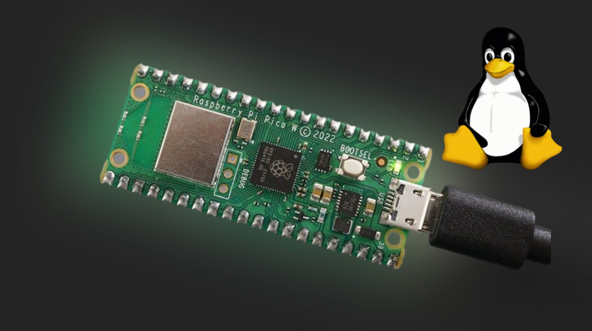
A Raspberry Pi Pico running real Linux, with its own keyboard and screen.
The RP2040 emulates a RISC-V CPU, SPI PSRAM becomes system memory,
and the Linux guest drives real GPIO pins.





Website • Try it • How it works • Build one • Programming • Downloads • PLAN.md
The story, photos, full pin map and wiring diagrams: flyboy-byte.github.io/riscv-pico
[!NOTE] This is a build log, not an upstream improvement. It's my own vibe-coded "Linux on a Pico" project — the real projects below did the hard work; this repo forks, ports, and glues them together and writes down what happened. Posted in case it's useful to someone chasing the same idea. The code, docs, and this README were written by Claude Code; I directed it, tested on real hardware, and made the calls.
| Project | What it gave this repo |
|---|---|
| tvlad1234/pico-rv32ima + tiny-rv32ima | The fork point. Actively maintained, the emulator core, and the VGA and PS/2 console code. |
| ElectroBoy404NotFound/pico-linux | The multi-chip PSRAM port and LCD console approach. |
| cnlohr/mini-rv32ima | The original RV32IMA-in-C emulator all of the above descends from. |
| xhackerustc/uc-rv32ima | The cache implementation this actually runs. |
| rswier/c4 via tvlad1234/c4 | The C compiler that runs on the machine itself. |
Go star their repos, not this one.
A Pico has no MMU and about 264 KB of RAM. It was never meant to run an operating system. So: core 1 of the RP2040 runs a full RV32IMA interpreter, two SPI PSRAM chips stand in for system memory, and an SD card holds the kernel and root filesystem. Linux boots on top of that — and custom kernel drivers let the guest reach back out through the emulator to drive real hardware.
Add a PS/2 keyboard, a VGA monitor and a breadboard power supply, and it runs with no computer attached. You can write a program in nano on the Pico, run it, and have it blink an LED.
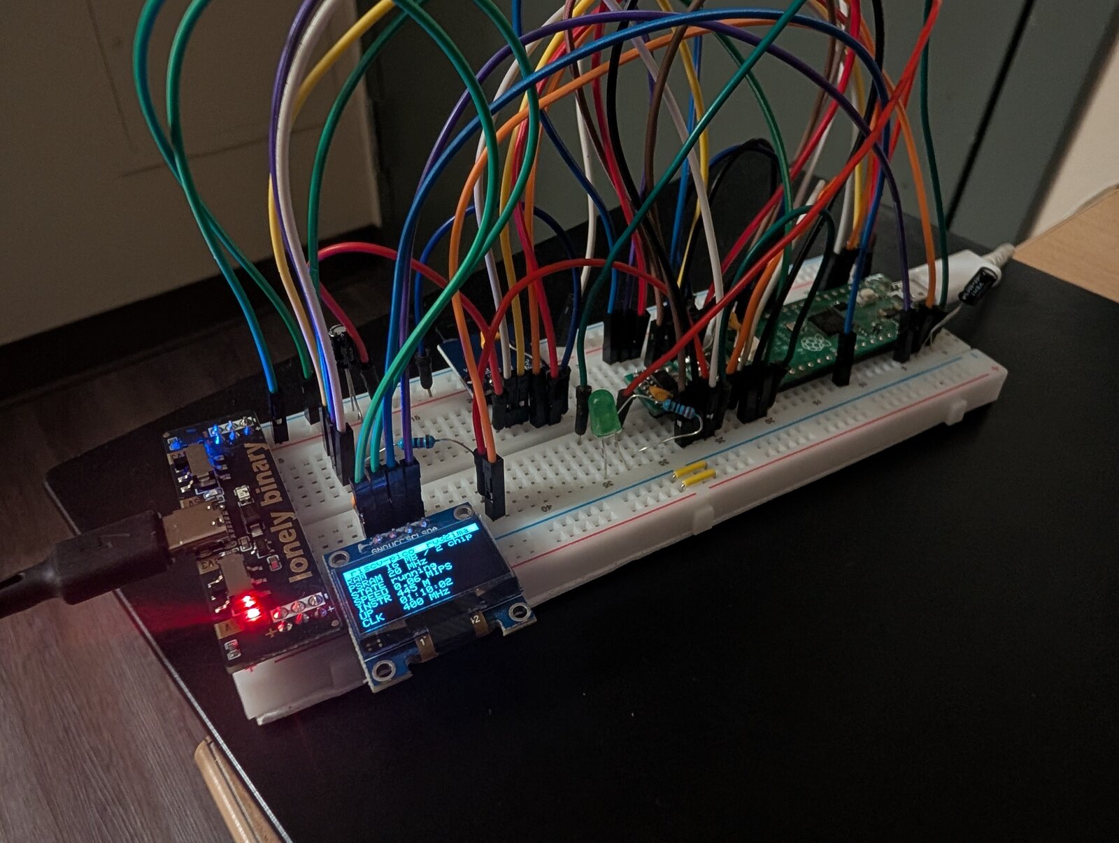
The OLED is reporting on the machine it's plugged into: 16 MB across 2 chips, live MIPS, uptime, 400 MHz clock.
And running on its own: PS/2 keyboard in, VGA monitor out, no PC anywhere.
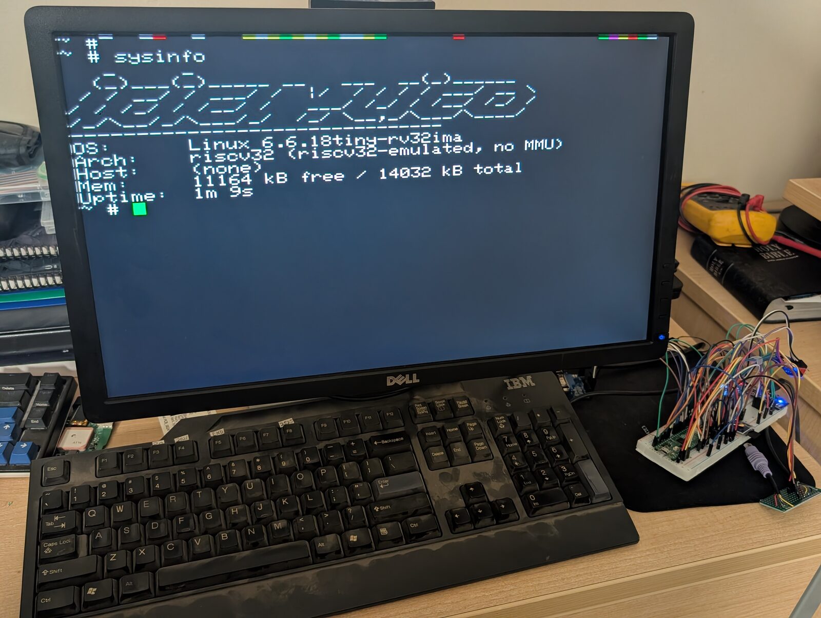 | 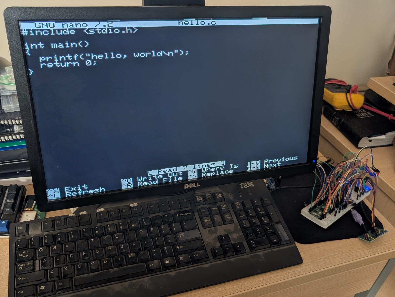 |
sysinfo: Linux 6.6 on an emulated RV32, 14 MB of RAM | GNU nano editing hello.c, full screen |
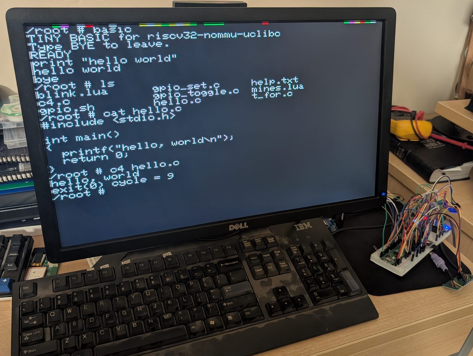 | 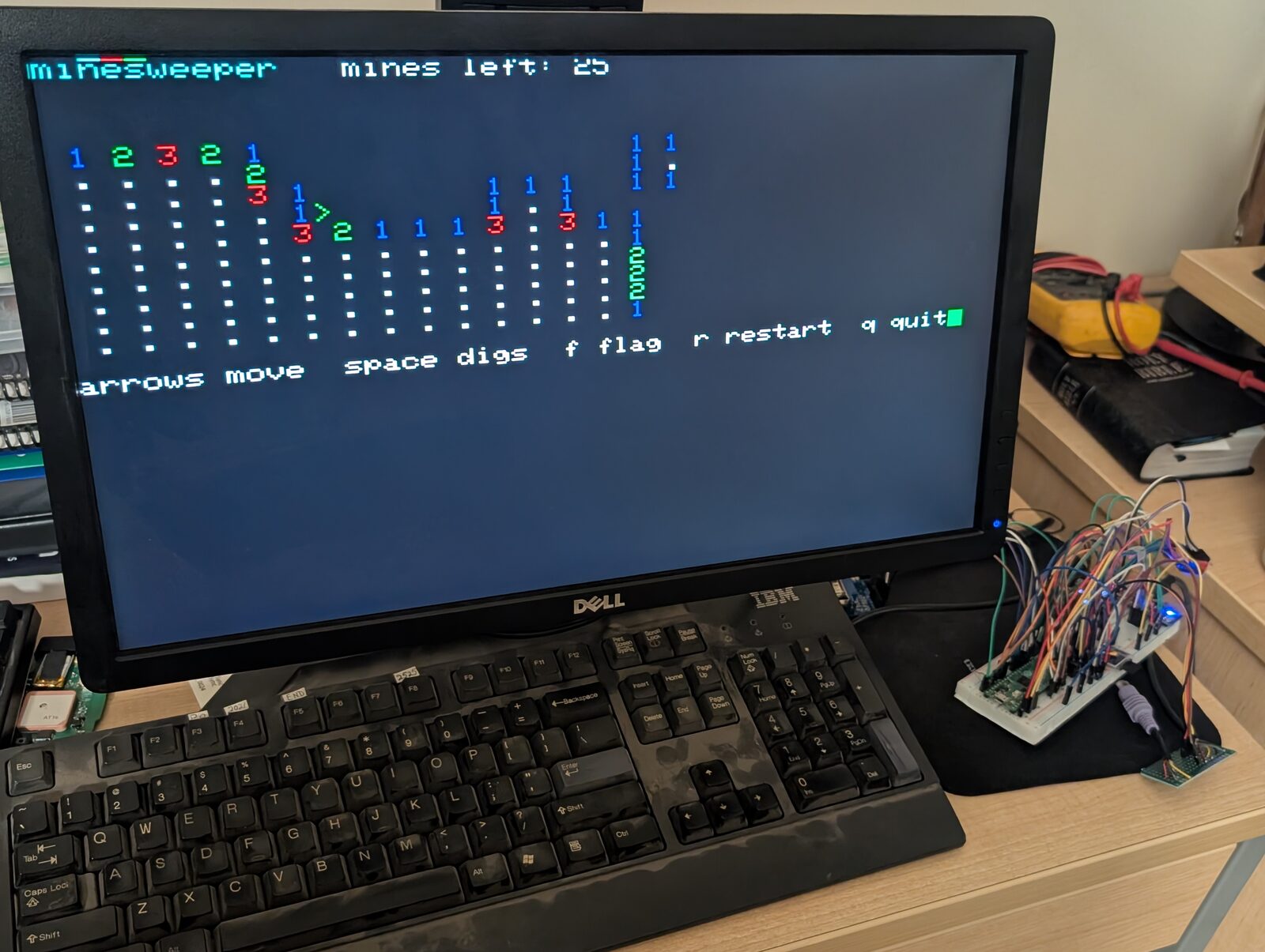 |
Tiny BASIC, then c4 compiling and running that hello.c | Minesweeper, in Lua |
What's actually verified, versus what merely compiles. No wishful thinking in this table.
| Feature | Notes | |
|---|---|---|
| ✅ | Linux boots on a real Pico | RP2040, 16 MB PSRAM, 60 MB rootfs off SD. Shell in well under a minute. |
| ✅ | Runs standalone | PS/2 keyboard in, VGA out, its own power supply. Files edited and saved with no PC attached. |
| ✅ | GPIO from Linux → real pins | Both /dev/gpiochipN (chardev + libgpiod) and /sys/class/gpio. Verified lighting an actual LED. |
| ✅ | Runs real software | Tiny BASIC, Lua 5.4.7, GNU nano 7.2 (full-screen), sysinfo, and minesweeper. |
| ✅ | nano on the VGA screen | Firmware v6 rewrote the VGA terminal as a VT102, so nano draws correctly at 53×30. Verified on hardware. On v5, nano over VGA is unusable. |
| ✅ | Custom kernel drivers | Block device, GPIO, second console channel — real Linux drivers, not shims. |
| ✅ | Desktop harness | Boots the same kernel on your PC in a few seconds. No hardware needed. |
| ✅ | SSD1306 OLED panel | A live stats visualizer. Not essential, just fun. |
| ✅ | Programming on the Pico | Lua with sleep and raw key input, GPIO from Lua and the shell, the c4 C compiler, BASIC's BYE, and minesweeper. All verified on hardware. |
| ✅ | Slimmer kernel | Networking removed, about 1 MB of RAM back. Boots on hardware. |
| 🚧 | pico2 / pico2_w (RP2350) | Builds clean for all four board targets. Never actually flashed. |
| ❌ | Networking on the Pico | Removed on purpose for the RAM. The stack and a half-built host bridge live on in net-v1. |
| ❌ | I²C / SPI / PWM / ADC for the guest | Documented as an idea in PLAN.md. Deliberately not built. |
A desktop build of the real emulator core, booting the same SD card image the Pico uses.
git clone https://github.com/flyboy-byte/riscv-pico && cd riscv-pico
harness/build.sh

mkdir images
REL=https://github.com/flyboy-byte/riscv-pico/releases/download/sdcard-v2
curl -L $REL/riscv-pico-sdcard-v2.tar.gz | tar xz -C images

# lay the three files out on a FAT image, the way the firmware expects
dd if=/dev/zero of=harness/disk.img bs=1M count=80
mformat -F -i harness/disk.img ::
mcopy -i harness/disk.img images/IMAGE images/DTB images/ROOTFS ::

python3 harness/desktop_terminal.py harness/disk.img
Needs mtools, plus PyQt6 and python-pyte (sudo pacman -S python-pyte on Arch). Boots to a
shell in a couple of seconds. Then try:
| Command | What happens |
|---|---|
lua /root/blink.lua 3 | Blinks GPIO line 0 three times. The harness prints each pin change |
c4 /root/hello.c | Compiles and runs C on the emulated machine |
basic | Tiny BASIC. BYE gets you back out |
lua /root/mines.lua | Minesweeper. Arrow keys, space digs, f flags, q quits |
nano, sysinfo, gpioinfo gpiochip0 | Editor, system banner, the GPIO chip |
[!IMPORTANT] These images won't boot under stock
mini-rv32ima. This project's emulator core adds custom block-device and console CSRs that upstream doesn't implement, soharness/build.shbuilds this repo's own desktop copy of the real core instead. Background in CLAUDE.md.
The interesting part isn't that Linux boots. It's that the emulated guest can reach real
hardware — so echo 1 > /sys/class/gpio/gpio512/value, typed into a Linux shell, ends with
current flowing out of a physical pin.
┌─────────────────────────────────────────────────────────────────┐
│  RISC-V Linux guest                                 (emulated)  │
│                                                                 │
│      shell  ·  BASIC  ·  Lua  ·  c4  ·  nano                    │
│                       │                                         │
│      Linux 6.6, nommu, RV32IMA                                  │
│                       │                                         │
│      drivers:  gpio-tinyrv32  ·  block  ·  console              │
└───────────────────────┬─────────────────────────────────────────┘
                        │   CSR instructions   (GPIO = 0x1a0-0x1a3)
┌───────────────────────┴─────────────────────────────────────────┐
│  RP2040  @ 400 MHz                              (real silicon)  │
│                                                                 │
│      core 1  ──▶  tiny-rv32ima, the RV32IMA interpreter         │
│      core 0  ──▶  CSR handlers, VGA, PS/2, OLED                 │
└───────────────────────┬─────────────────────────────────────────┘
                        │
     ┌──────────────────┼──────────────────┬──────────────────┐
     ▼                  ▼                  ▼                  ▼
 2x SPI PSRAM      microSD card        GPIO pins        console I/O
 16 MB = RAM     kernel + rootfs     LEDs, buttons    PS/2, VGA, OLED
Linux sees ordinary devices — a block device, a gpiochip, a console. The RP2040 does the
translating underneath. Full GPIO walkthrough, including wiring an LED and the exact ioctls, is in
docs/GPIO_AND_BASIC_TUTORIAL.md. The
website draws the whole machine, including where
the 16 MB of memory actually lives.
The whole path, start to finish. No compiler needed: the firmware and the SD card image are both prebuilt.
| Step | Do this | Where |
|---|---|---|
| 1 | Buy the parts | Parts |
| 2 | Wire it: PSRAM and SD card first, keyboard and VGA after | Wiring |
| 3 | Flash the firmware: hold BOOTSEL, plug in, copy one .uf2 file | Firmware |
| 4 | Put three files on a FAT32 microSD card | SD card |
| 5 | Power on, press any key, wait for the ~ # prompt | First boot |
| 6 | Blink an LED, edit a file, play minesweeper | Programming on the Pico |
Everything here is what's on the verified build. No minimum order quantities, all single-quantity friendly. Prices drift; this isn't a live feed.
| Part | Qty | Notes |
|---|---|---|
| Raspberry Pi Pico | 1 | Verified on a Pico H (RP2040). Builds for pico_w/pico2/pico2_w too, but RP2350 is untested. |
| APS6404L-3SQR-SN PSRAM, SOP-8 | 2 | 8 MB each → 16 MB. ProtoSupplies, ~$2.39 ea. |
| SMD→DIP 8-pin adapter | 1 pack | ~$0.79 for 5. Headers not included. The PSRAM is surface-mount; these get it onto 0.1" pitch. |
| microSD breakout, SPI | 1 | Any 3.3 V module labelled 3V3 CS MOSI CLK MISO GND. |
| microSD card | 1 | 4–32 GB, FAT32. Not SDXC/exFAT — Petit FatFs only speaks FAT12/16/32. |
| 10 kΩ resistor | 1 | Pull-up for SIO2/SIO3 on both chips. One resistor covers all four pins. |
| SSD1306 OLED, 128×64 | 0–1 | Optional. Must be the I²C 4-pin variant, not SPI. |
| Decoupling caps | a few | 100 nF ceramic + 10–100 µF bulk. Cheap insurance — see the power warning below. |
| Breadboard + jumpers | — | |
| Micro-USB cable | 1 | Flashing the firmware, and the serial console. |
To run it without a PC, add:
| Part | Qty | Notes |
|---|---|---|
| Serial Wombat PCB_0024 VGA breakout | 1 | Resistors already fitted. Plug in an ordinary VGA cable; six jumpers to the Pico. |
| VGA monitor + cable | 1 | Anything that takes 640×480 at 60 Hz. |
| PS/2 keyboard | 1 | A real PS/2 keyboard, not a USB keyboard on a passive purple adapter. |
| PS/2 socket breakout | 0–1 | Or do what this build did: cut the keyboard's cable and solder its four wires to a scrap of perfboard with jumper wires. |
| Logic level converter, BSS138 4-channel | 1 | PS/2 is a 5 V bus. Only the keyboard needs it. |
| USB-C breadboard power supply | 1 | 5 V rail powers the Pico and keyboard; 3.3 V rail powers the SD card and OLED. |
[!CAUTION] Get the
-SN(SOP-8) suffix, not-ZR. Same silicon, but-ZRis USON-8 — a 3×2 mm leadless package that is genuinely painful to hand-solder or rework. PlainAPS6404L-3SQRwith no suffix is bare die, not a packaged part at all.
Substitutes work fine. ESP-PSRAM64H, LY68L6400, and IPUS equivalents share the SOP-8 pinout and
the 0x5D known-good-die ID the firmware checks for. For stock across distributors, try
Findchips or
Octopart.
The core build is 3.3 V native and its console is USB serial, so no adapter is needed. The website has the full 40-pin map, a power and ground diagram, and a VGA wiring bench card.
[!WARNING] On the SD card module,
MOSIandCLKcross over. The module's header order does not match the Pico's pin order. This is the single easiest mistake to make on the whole board, and it costs you an afternoon.
[!WARNING] The PS/2 keyboard runs at 5 V, and RP2040 pins are not 5 V tolerant. Route
CLKandDATAthrough the level converter. Before the Pico is connected, meter the converter's low-voltage outputs: they must idle at 3.3 V, never 5 V. A resistor divider does not work on this bus.
They differ only in chip-select:
| Chip pin | Signal | Chip 1 | Chip 2 |
|---|---|---|---|
| 1 | /CE | GP13 (pin 17) | GP14 (pin 19) |
| 2 | SO | GP12 (pin 16) | GP12 — shared |
| 5 | SI | GP11 (pin 15) | GP11 — shared |
| 6 | SCLK | GP10 (pin 14) | GP10 — shared |
| 3, 7 | SIO2, SIO3 | → 3V3 via one shared 10 kΩ | same |
| 4, 8 | VSS, VDD | GND, 3V3 | GND, 3V3 |
SIO2/SIO3 go unused in SPI mode. Pull them high, not low — some pin-compatible parts put an
active-low /RESET or /HOLD on SIO3. One 10 kΩ covers all four pins; nothing ever drives them.
Default build is two-chip / 16 MB (PSRAM_TWO_CHIPS 1 in hw_config.h, EMULATOR_RAM_MB 16 in
vm_config.h). Going single-chip? Set them to 0 and 8. Mismatching them is a compile-time
#error, not a silent address-wrap bug that bites you three hours later.
PSRAM_SPI_SPEED_MHZ defaults to 20, which stays stable even on messy breadboard leads.
| Module | Pico |
|---|---|
CS | GP0 (pin 1) |
MOSI | GP3 (pin 5) |
CLK | GP2 (pin 4) |
MISO | GP4 (pin 6) |
⚠️ MOSI and CLK cross over — see the warning above. The module's header order does not
match the Pico's pin order.
The card itself is plain FAT32 with IMAGE, DTB, and ROOTFS in the root. No special
formatting.
| Keyboard (mini-DIN-6) | Converter | Pico |
|---|---|---|
Pin 1, DATA | HV1 → LV1 | GP26 (pin 31) |
Pin 5, CLK | HV2 → LV2 | GP27 (pin 32) |
| Pin 4, +5 V | HV | 5 V rail of the breadboard supply |
| Pin 3, GND | GND | Common ground |
| — | LV | 3V3 OUT (pin 36) |
Wire colours are not standardised, so identify pins with a meter rather than by colour. Getting
DATA and CLK swapped is harmless; if no keys arrive, swap them. The driver only receives, so
Caps Lock and Num Lock lights never come on. No firmware change is needed — the keyboard driver is
already in the firmware.
Use the breakout's outer header column, which is its 3.3 V input. The inner column is sized for 5 V and gives a dim picture.
| Breakout | Pico |
|---|---|
V | GP16 (pin 21) |
H | GP17 (pin 22) |
GND header | GND (pin 23) |
R | GP18 (pin 24) |
G | GP19 (pin 25) |
B | GP20 (pin 26) |
Reading the column bottom to top lands on the Pico's pins in order, so the jumpers run straight. Leave the five round pads along the top and the solder jumpers on the back unconnected. Green and blue aren't configurable in firmware: they always follow red on the next two pins. The picture is 320×240 in eight colours, and the terminal is 53×30 characters.
Four separate jumpers — there's no free adjacent GPIO pair left on the board:
| Module | Pico |
|---|---|
VCC | 3.3 V from a separate supply, not pin 36 — see the power warning below |
GND | GND (pin 28), tied to that supply's ground at one point |
SDA | GP28 (pin 34) |
SCL | GP21 (pin 27) |
Shows RAM/PSRAM config, boot stage, live MIPS, uptime, and clock — a stats panel, not a second
console. It runs on core 0, which the emulator never touches, and probes at boot: with nothing
attached, the firmware behaves exactly as if the code weren't there. Disable entirely with
CONSOLE_OLED 0 in hw_config.h. If a panel is wired but stays blank, try OLED_I2C_ADDR 0x3D.
It runs alongside VGA without conflict.
Feed the breadboard supply's 5 V rail into VSYS (pin 39). Never feed 3.3 V into pin 36: that
is the output of the Pico's own regulator, not an input. With USB unplugged there's no serial
console, so the VGA screen shows the boot. Before pulling power, run sync or halt, or the ext2
root filesystem can be damaged.
[!WARNING] Breadboard power is the thing that will actually bite you. Wiring up the OLED destabilised the PSRAM bus and crashed boot — despite the two sharing no GPIO pins at all. The cause was a single 3V3 supply pin feeding PSRAM VCC, both chips' pull-ups, the SD card and the OLED, so any load spike on that node bled into everything else on it.
The fix was a single-point (star) power layout: separate supply for OLED/SD, PSRAM on its own clean VCC/GND, short jumpers, and decoupling caps at each chip's supply pins. If you see random resets or PSRAM failures that only appear once a second peripheral is wired up, check power distribution before you suspect the chip. Full writeup — including the wrong theories tried first — in PLAN.md and docs/HARDWARE_SCHEMATIC.md.
Just want to flash something? Grab
pico-rv32ima-boards-v6
— prebuilt .uf2 for all four board variants, ready to go. It includes the VGA, PS/2 and OLED
consoles, and a VGA terminal that full-screen programs like nano can draw on.
# once — Pico SDK, shallow clone with just the tinyusb submodule (~65 MB)
git clone -b 2.1.1 --depth 1 https://github.com/raspberrypi/pico-sdk.git ~/pico-sdk
git -C ~/pico-sdk submodule update --init --depth 1 lib/tinyusb

firmware/build.sh              # all four boards → firmware/out/*.uf2
firmware/build.sh pico2_w      # or just one
About 150 KB per board. Flash by holding BOOTSEL while plugging in the Pico — it mounts as a
USB drive called RPI-RP2 — then copy the .uf2 across.
sdcard-v2, download IMAGE, DTB and ROOTFS. The same three
files are also bundled as riscv-pico-sdcard-v2.tar.gz.Plug the Pico into a PC over USB and open its serial console: screen /dev/ttyACM0 115200 on
Linux, or PuTTY on the new COM port on Windows. With the VGA screen attached you can skip this and
watch the monitor instead.
PSRAM OK, then SD init OK, and waits for a keypress. Press any key,
on the serial console or on the PS/2 keyboard. On the VGA screen, all you see before that is
the pico-rv32ima, compiled … banner.Loading kernel image, then Starting RISC-V VM, then the Linux boot log.~ # shell prompt, in well under a minute. Try sysinfo.Before unplugging, type halt, or at least sync. The root filesystem is ext2 and doesn't
survive a hard power-off well.
| You see | Likely cause |
|---|---|
| Nothing at all over USB serial | Firmware not flashed, or the console opened too late. Press a key; the boot waits for one anyway. |
PANIC: PSRAM ERR, repeating | PSRAM wiring or power. Check /CE on GP13/GP14, the 10 kΩ pull-up, and that each chip has 3.3 V and ground. |
PANIC: Error initalizing SD | MOSI/CLK swapped (the most common mistake), the card isn't FAT32, or the module isn't 3.3 V. |
PANIC: Error opening image file | The card is readable but IMAGE isn't in its root, or it was renamed. |
| Boots, then random resets once the OLED or SD is added | Power distribution. See the warning above. |
| VGA monitor says "no signal" | Check V and H on GP16/GP17 and the ground jumper. The monitor must accept 640×480 at 60 Hz. |
| Keyboard does nothing | Swap DATA and CLK. Check the converter's low side idles at 3.3 V. |
System hasn't been cleanly shutdown | Harmless warning after a power-off without halt. |
You can write and run programs on the machine itself: open a file in nano, save it, run it. No PC.
| Language | Try | Notes |
|---|---|---|
| Lua 5.4 | lua blink.lua | Adds sys.sleep(seconds), sys.ms() and sys.raw(), which stock Lua lacks. GPIO goes through /sys/class/gpio. |
| C, via c4 | c4 gpio_set.c 1 | Compiles C to bytecode and interprets it. This copy adds for and write, and it can compile itself. |
| Tiny BASIC | basic | Line-numbered BASIC. BYE returns to the shell. |
| Shell | sh script.sh | busybox hush, not bash. |
Every command for all of this is on one page in
docs/CHEATSHEET.md. A shorter copy sized for the VGA screen is on the card:
nano -v /root/help.txt pages through it when there's no PC attached.
The examples are in /root on the SD image. Blinking an LED in Lua looks like this:
local function put(path, text)
  local f = io.open(path, "w"); f:write(text); f:close()
end

put("/sys/class/gpio/export", "512")                 -- GPIO line 0 = Pico GP1, pin 2
put("/sys/class/gpio/gpio512/direction", "out")
for i = 1, 10 do
  put("/sys/class/gpio/gpio512/value", "1"); sys.sleep(0.2)
  put("/sys/class/gpio/gpio512/value", "0"); sys.sleep(0.2)
end
put("/sys/class/gpio/unexport", "512")               -- release it, or gpioset says busy
There's a game, too: lua /root/mines.lua is minesweeper on the VGA screen. Arrow keys move,
space digs, f flags, r restarts, q quits. Board size is optional —
lua /root/mines.lua 20 14 40. Single keypresses need sys.raw(), another call the Lua build adds;
where that isn't available it falls back to typed commands, so it works over a pipe too.
os.execute and io.popen don't work from Lua here: they need fork(), which a no-MMU machine
doesn't have. Details on c4's language and limits are in
apps/c4/README.md.
There's a real cross-compiler for this target — riscv32-buildroot-linux-uclibc-gcc, producing the
bFLT no-MMU binary format the kernel needs. apps/ holds the hand-written pieces: Tiny BASIC
(basic.c), the Lua sys extension (lua_sys.c), c4, a GPIO chardev smoke test (gpiotest.c),
and sysinfo.sh. Lua 5.4.7 and GNU nano 7.2 build straight from unmodified upstream sources and
aren't vendored here.
The toolchain isn't checked in; grab
toolchain-v2. The rebuild
recipe and the gotchas already solved live in PLAN.md's "Cross-compile toolchain", "Real GNU nano"
and "apps/" sections.
Build outputs ship as GitHub releases rather than committed binaries, which keeps git clone fast.
| Release | Contents |
|---|---|
sdcard-v2 | Current SD card image. No-network kernel; rootfs with Lua, c4, BASIC and examples, with the console sized for the VGA screen. Hardware-verified. |
pico-rv32ima-boards-v6 | Current firmware, all four boards — 16 MB two-chip, VGA with a rewritten VT102 terminal, PS/2 with working Home/End/Delete/Page keys, OLED panel, GPIO CSRs. |
toolchain-v2 | The cross-compiler, wchar-enabled (needed for nano/ncurses). |
rv32harness-v1 | Desktop harness binaries, x86-64 Linux. |
kernel-gpio-v2 | Previous kernel + rootfs, with networking. Hardware-verified. |
net-v1 | The networking reference: TCP/IP stack and the second console channel's SLIP work. |
apps-v1, apps-v2 | Older loose binaries. Everything current is in sdcard-v2. |
Firmware -v5 boots sdcard-v2, but nano on its VGA screen is unusable. -v3/-v4 still boot
too. -v1/-v2 are superseded single-chip 8 MB builds that don't boot the current rootfs.
| Path | What | Notes |
|---|---|---|
harness/ | this repo | Desktop build of the real emulator core, plus a PyQt6 terminal app to drive it. |
firmware/ | this repo | build.sh — one command, .uf2s for all four board targets. |
apps/ | this repo | Programs for the target: Tiny BASIC, the Lua sys extension, examples. |
apps/c4/ | rswier via tvlad1234 | The on-device C compiler, with for and write added here. GPL-2.0. |
buildroot-overlay/ | this repo | Kernel config and the patches that create every custom device — block, GPIO, second console. |
site/ | this repo | The website. Plain HTML, published to gh-pages. |
docs/ | this repo | GPIO and BASIC tutorial, hardware schematic handoff notes, images. |
experiments/ | this repo | Side quests, like a Raspberry Pi 4 pretending to be an SD card. |
upstream/pico-rv32ima/ | tvlad1234 | The fork this builds on. No longer pristine — the PSRAM port lives here. |
upstream/pico-rv32ima/tiny-rv32ima/ | tvlad1234 | The emulator core. Also edited by the same port. |
upstream/pico-linux/ | ElectroBoy404NotFound | Reference only, still pristine. Source of the PSRAM port logic. |
All three upstream/ paths are git subtrees with full history, so git log -- upstream/<x> works
and upstream changes can still be pulled — commands in CLAUDE.md.
PLAN.md is the living state doc — every decision, every bug, every dead end, and what's next. It's far more detailed than this file.
This repo's own code (harness/, apps/, firmware/, buildroot-overlay/, site/, docs) is MIT —
see LICENSE — except apps/c4/, which is GPL-2.0 like the c4 it comes from. Everything
under upstream/ keeps its original licensing (MIT / Apache-2.0 / BSD-3); see the LICENSE in each
subtree.
| Qty | Value | Footprint | References |
|---|---|---|---|
| 4 | 10k | R_Axial_DIN0207_L6.3mm_D2.5mm_P7.62mm_Horizontal | R1, R2, R3, R4 |
| 2 | BSS138 4ch level converter - | PinSocket_1x06_P2.54mm_Vertical | J_LVL_HV, J_LVL_LV |
| 2 | PSRAM APS6404L on DIP-8 adap | DIP-8_W7.62mm_Socket | U_RAM1, U_RAM2 |
| 1 | 100n RAM1 | C_THT_P2.54mm | C1 |
| 1 | 100n RAM2 | C_THT_P2.54mm | C2 |
| 1 | 10u bulk | C_THT_P5.08mm | C3 |
| 1 | 3-way screw terminal 2.54mm | TerminalBlock_Phoenix_MPT-0,5-3-2.54_1x03_P2.54mm_Horizontal | TB1 |
| 1 | PS/2 socket breakout | PinSocket_1x04_P2.54mm_Vertical | J_PS2 |
| 1 | Pico L | PinSocket_1x20_P2.54mm_Vertical | J_PICO_L |
| 1 | Pico R | PinSocket_1x20_P2.54mm_Vertical | J_PICO_R |
| 1 | SSD1306 128x64 0.96in | PinSocket_1x04_P2.54mm_Vertical | J_OLED |
| 1 | Serial Wombat PCB_0024 VGA b | PinSocket_1x06_P2.54mm_Vertical | J_VGA |
| 1 | microSD SPI breakout | PinSocket_1x06_P2.54mm_Vertical | J_SD |
It measures 90 × 70 mm and has 2 copper layers, 1.6 mm thick.
18 parts. The full list of its parts is on this page, with links to each part's symbol and footprint where PCBKit's library has them.
From the flyboy-byte/riscv-pico repository on GitHub, at the commit this page was made from: the board is hardware/carrier/carrier_proto.kicad_pcb. PCBKit opens the board in the browser, with nothing to install.
Its repository publishes it under the MIT licence: you may reuse it on that licence's terms (keep the author's notice, and for a copyleft licence share your changes alike).

VoronDesign/Voron-Hardware
Cool Hardware designed by the Voron Design group


hackclub/OnBoard
💡 Join 1,000 teenagers and make your first PCB with a $100 grant!

VoronDesign/Voron-Tap
Tap is a nozzle-based z-probe for the V2 and Trident printer designs. The entire toolhead moves to trigger an optical switch. Tap offers many advantages:

Luos-io/luos_engine
Open-source and real-time orchestrator for cyber-physical-systems, to easily design, test and deploy embedded applications and digital twins.


Twotoz/C5VRX
Ultra-minimal, zero-CPU 5.8 GHz analog FPV video receiver using ESP32-C5 Wi-Fi 6 PHY MODEM_DIAG, BitScrambler WBFM demodulation & resistor DAC CVBS