2 layers

 flaviut/led-dimmer2
Open-source hardware for dimming LED strips, using ESPHome software
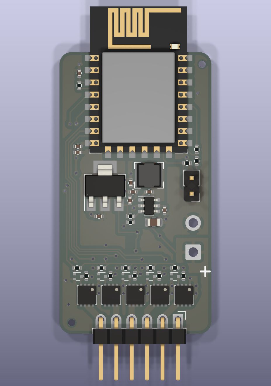
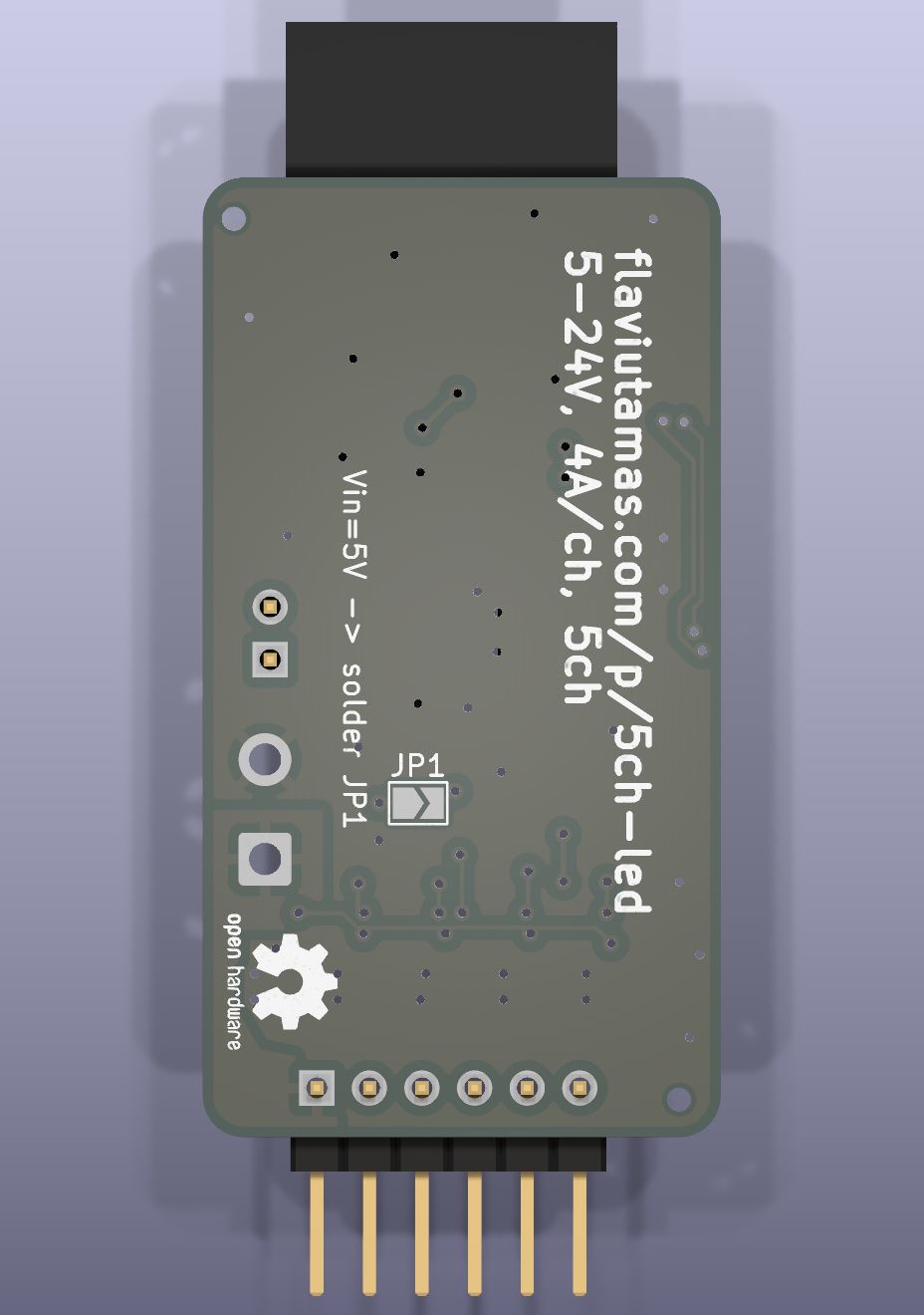
Dimmer is an open-source printed circuit board by flaviut, from the flaviut/led-dimmer repository on GitHub. It is a 2-layer board of 25 × 46.3 mm with 47 parts on 37 nets, routed with 242 tracks and 61 vias.
It is built around the ESP-12F, RY8310 and AMS1117-3.3, with the HY1503C1 and WNM2030 among its other parts. Its parts include 16 resistors, 10 capacitors, 10 transistors, 3 ICs and 3 connectors. It belongs with the home automation and IoT and lEDs and displays boards and the ESP8266 boards of this library.


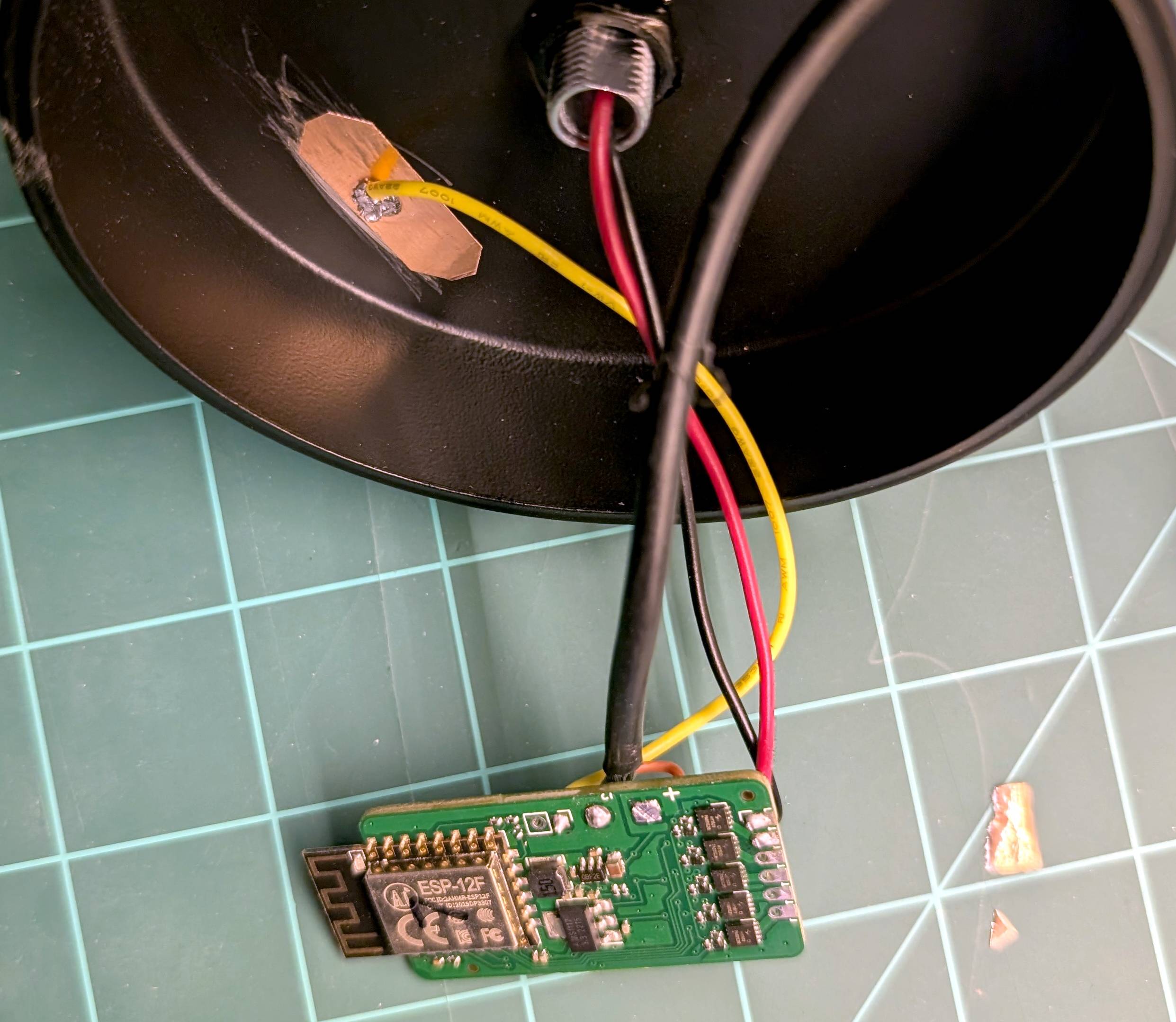
Designed for use with ESPHome, this project is a compact & powerful dimmer for all LED strips. The primary goal was low cost, in the most compact package possible. For scale, the picture above was taken on a 1 inch grid.
This is intended as a substitute for the poorly-designed Magic Home LED strip controllers.
Note: the yellow wire in the photo does not work as a capacitive touch sensor, that was a failed experiment.
| Qty | Value | Footprint | References |
|---|---|---|---|
| 8 | 10k | Resistor_SMD:R_0402_1005Metric | R1, R2, R6, R7, R8, R9, R10, R11 |
| 6 | 2.4k | Resistor_SMD:R_0402_1005Metric | R3, R12, R13, R14, R15, R16 |
| 5 | 10u | Capacitor_SMD:C_0402_1005Metric | C3, C4, C5, C7, C9 |
| 5 | HY1503C1 | Library:DFN-8-1EP_3x3mm_P0.65mm_EP2x2.4mm | Q6, Q7, Q8, Q9, Q10 |
| 5 | WNM2030 | Package_TO_SOT_SMD:SOT-723 | Q1, Q2, Q3, Q4, Q5 |
| 4 | 100n | Capacitor_SMD:C_0402_1005Metric | C1, C2, C6, C8 |
| 2 | MountingHole | Library:ToolingHole | H1, H2 |
| 1 | 10u 50V | Capacitor_SMD:C_0805_2012Metric | C10 |
| 1 | 15uH 750mA | Inductor_SMD:L_Bourns-SRN4018 | L1 |
| 1 | 1k | Resistor_SMD:R_0402_1005Metric | R4 |
| 1 | 51k | Resistor_SMD:R_0402_1005Metric | R5 |
| 1 | AMS1117-3.3 | Package_TO_SOT_SMD:SOT-223-3_TabPin2 | U2 |
| 1 | Conn_01x02 | Connector_PinHeader_2.54mm:PinHeader_1x02_P2.54mm_Vertical | J1 |
| 1 | Conn_01x02 | Connector_Wire:SolderWire-0.75sqmm_1x02_P4.8mm_D1.25mm_OD2.3mm | J2 |
| 1 | Conn_01x06 | Library:PinHeader_1x06_P2.54mm_Horizontal | J3 |
| 1 | ESP-12F | RF_Module:ESP-12E | U1 |
| 1 | Logo_Open_Hardware_Small | Symbol:OSHW-Logo2_7.3x6mm_SilkScreen | LOGO1 |
| 1 | RY8310 | Package_TO_SOT_SMD:TSOT-23-6 | U3 |
| 1 | SolderJumper_2_Open | Jumper:SolderJumper-2_P1.3mm_Open_TrianglePad1.0x1.5mm | JP1 |
It measures 25 × 46.3 mm and has 2 copper layers, 1.6 mm thick.
47 parts, built around the ESP-12F, RY8310, AMS1117-3.3 and HY1503C1. The full list of its parts is on this page, with links to each part's symbol and footprint where PCBKit's library has them.
From the flaviut/led-dimmer repository on GitHub, at the commit this page was made from: the board is dimmer.kicad_pcb and its schematic dimmer.kicad_sch. PCBKit opens the board in the browser, with nothing to install.
Its repository states no licence, so its author keeps all rights: ask flaviut before reusing the design.


RainbowLabsDE/LightInstallationController
PCB and Firmware of our first universal RGB light installation controller.

RainbowLabsDE/PowerMeasure_1Ph
this repo is still undergoing major changes and should not yet be rebuilt

crexodon/LED-Window-Matrix-Neo
Turning the campus building into a led display


klaus-liebler/sensact
Es gibt vier Namespaces für Nachrichten "REQUEST" und "RESPONSE", "EVENT" und "ACKNOWLEDGE". Dies wird mit den beiden LSB des Versions-Namespace-Bytes erklärt (Somit bleiben 64 Versionierungsmöglichkeiten) Alle vier…