Skip to the content
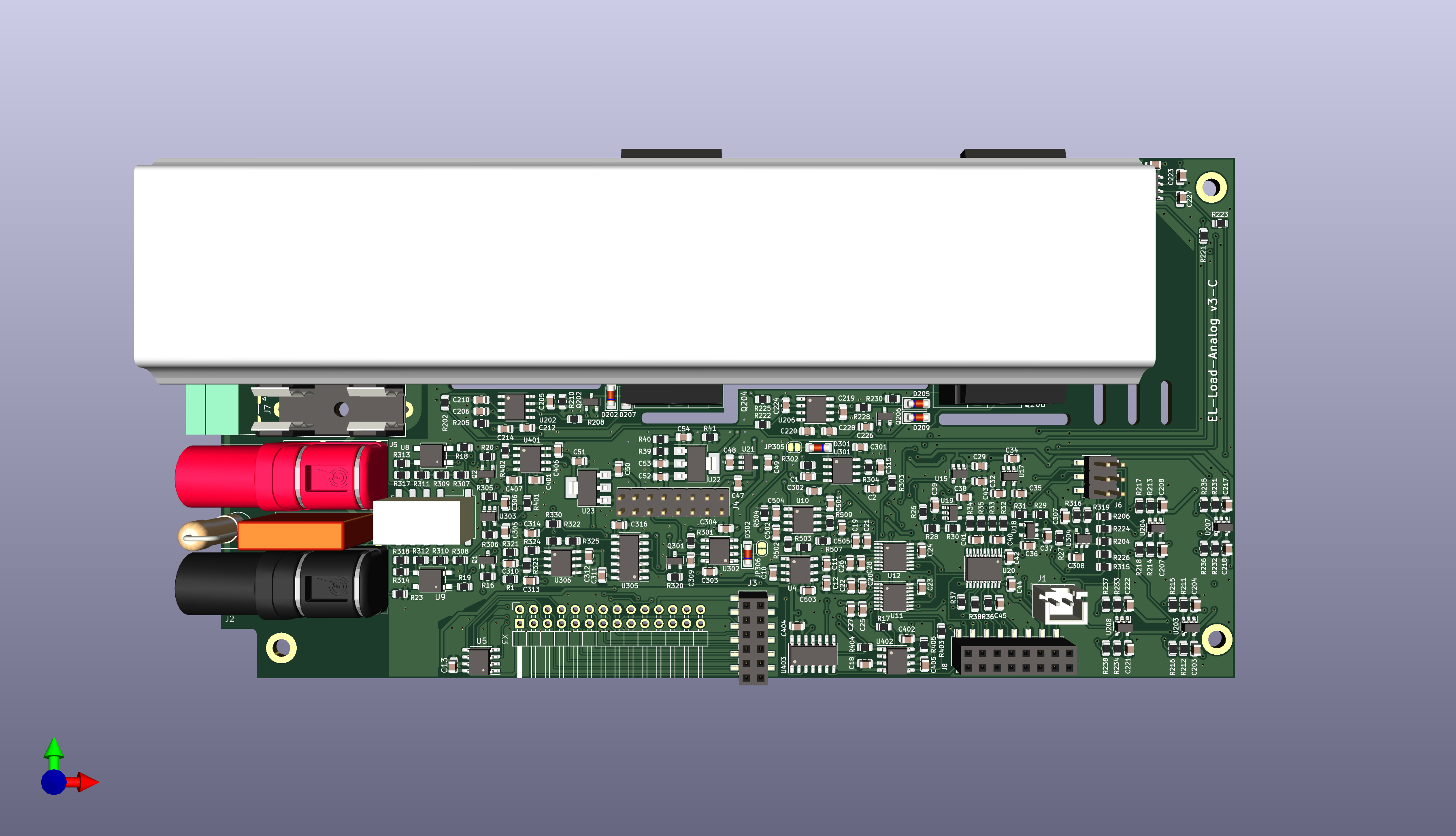
4 layers185 × 95 mmEL Load Analog, the printed circuit board in 3D

EL Load Analog

fietser28/EL-Load15

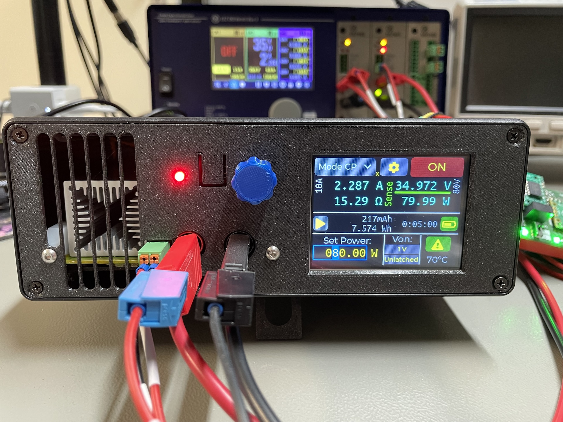
The DCL8010 electronic load module features a DC Electronic Load with several modes and protections. This project is the for the development boards for this project. There is a seperate git project for the firmware.

Size
185 × 95 mm
Copper layers
4
Thickness
1.57 mm
Parts
344
Nets
232
Pads
963
Tracks, vias
2,930, 477
Pours
21
Routed
Yes
KiCad
KiCad 7 (file 20221018)
Created
26 Dec 2023
Updated
27 Jul 2025

Overview

EL Load Analog is an open-source printed circuit board by fietser28, from the fietser28/EL-Load repository on GitHub. It is a 4-layer board of 185 × 95 mm with 344 parts on 232 nets, routed with 2,930 tracks and 477 vias.

It is built around the MCP6V51-E/OT, LM318D and DAC8555IPW, with the AD8038AR, ADS131M02IPW and LM393AP among its other parts. Its parts include 132 resistors, 99 capacitors, 27 ICs, 26 diodes and 16 transistors.

Main components

12

README

README.md

This is WORK IN PROGRESS.

The designs here are not finished or fully tested yet.

Overview

The DCL8010 electronic load module features a DC Electronic Load with several modes and protections. This project is the for the development boards for this project. There is a seperate git project for the firmware.

Standalone unit

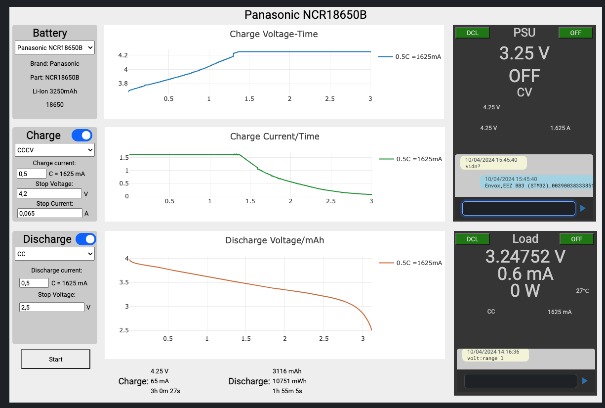
Together with [studio] and a BB3 there will be some example dashboards in the near future. For example a battery profile application:

Specifications

  • Modes: Constant Current (CC), Constant Voltage (CV), Constant Power (CP) and Constand Resistance (CR). CC and CV are implemented in hardware, CP and CR are software controlled and have a slower dynamic response.

  • Limits:

    • Current: 1mA - 10A set and read
    • Voltage: 0.5V - 80V (set), 1mV-80V read
    • Power: 80W
  • Protections: In hardware:

    • User definable Over Voltage Protection (OVP), clamps load off within 1ms
    • User definable Over Current Protection (OCP), clamps load off within 1ms With software support:
    • User definable Over Power Protection for a specific time in seconds (1-99)
    • User definable Over Temperature Protection for a specific time in seconds (1-99)
  • Other hardware features:

    • Von: The minimum voltage needs to be present before the load is turned on. This can be set with or without latching. This is implemented in hardware and when on guarentees a gradual turn-on if a power source is 'hot plugged' or turned on.
    • Temperature based fan control
    • Fan RPM readout
    • Heatsink temperature readout

Design considerations

Sizing

The Electronic Load was designed to complement a pair of BB3 DCP405 modules. Such a pair can deliver up to 80V (series configuration) or 10A (parallel configuration). The power is just maximized what is achievable with the small form factor of a BB3 module.

Minimum set voltage (an von cutoff) aim is as low as possible but at least 0.5V. A low Von cutoff is important to discharge for example AA battries (around 0.8V).

Resolution and accurary

Aim is to have 0.1% full scale accurary after calibration. Calibration will be done in 100% in software.

This results in the follwing goals:

Input/outputRangeAccuracyResolutionRemarks
Current monitor0-10A10mA1mA
Current monitor0-1A1mA0.1mAnot evaluted/tested yet
Voltage monitor0-80V80mV1mVAccuracy probably: 10mV
Voltage monitor0-10V1mV0.1mV
Power measurements0-24h1s & 0.2% FS1sPerform accurate incremental calculations and timing
Current set5mA-10A10mA1mA
Current set5mA-1A1mA0.2mA
Voltage set0.5-80V80mV1mV
Voltage set0.5-9V5mV1mV
Resistance set???0.5% FS In software
Power set?0.25W?0.5% FS in software
Von set (80V range)0.25-50V0.2V0.1VDifficult to calibrate
Von set (9V range)0.25-6V0.1V0.1VDifficult to calibrate
OCP (10A range)0.1-10A100mA10mADifficult to calibrate
OCP set (1A range)0.25-6V10mA1mADifficult to calibrate, not implemnted yet
OVP (80V range)1-80V0.2V0.1VDifficult to calibrate
OVP set (9V range)0.25-9V0.1V0.1VDifficult to calibrate, not tested yet

Using 16bit ADC's and DAC's this should be achievable with calibration done in software.

Hardware / software partitioning

Everything requiring a response below 10ms is implemented directly in hardware. All other functionality is preferably done in software. This results in the following decisions:

  • Current and Voltage measurement and control loops are in analog circuitry
  • Over voltage and over current protection measurement and shutdown are in hardware with a seperate clamp on the power MOSFET gates to shutdown as fast as possible. It is up to software to toggle pins to release the hwardware protection
  • Von circuitry is implemented in hardware including the latch. The Von circuitry is important to avoid the MOSFET loops to go fully open (unregulated) when the supplied current and/or voltage is less then the set values. An unregulated situation would lead to large (= overshoot) spikes if the DUT suddenly starts providing more power (e.g. plug-in/turn on).
  • To combine current, voltage and Von control a cross-over circuit is used where the smallest set current will get priority.

Fail safely:

An electronic load is often used to discharge batteries and due to the time this takes it is not realistic to assume the discharge is always attended by a person. If a failing component in the electronic load fails it might cause a short. A battery (or other power source without proection) being shorted is a serious fire hazard. Therefore the Electronic Load has a physical fuse and all possbile components that might faile are behind this fuse. This includes the input snubber network, transient and revserse polarity diode and of course the main MOSFETS of the electronic load. This protection is not perfect: It requires a >10A peak surge, but greatly reduces the risk.

Limitations / Issues

Most limitations,TODO's and issues are now tracked on github issues.

PCBs

EL-Load-Analog

Main PCB. Contains all the analog circuitry including MOSFETS. The DAC & ADC's are also on this board. Sizes of the PCB adhere to DIB standard (I hope).

EL-Load-Analog

EL-Load-Power-MCU

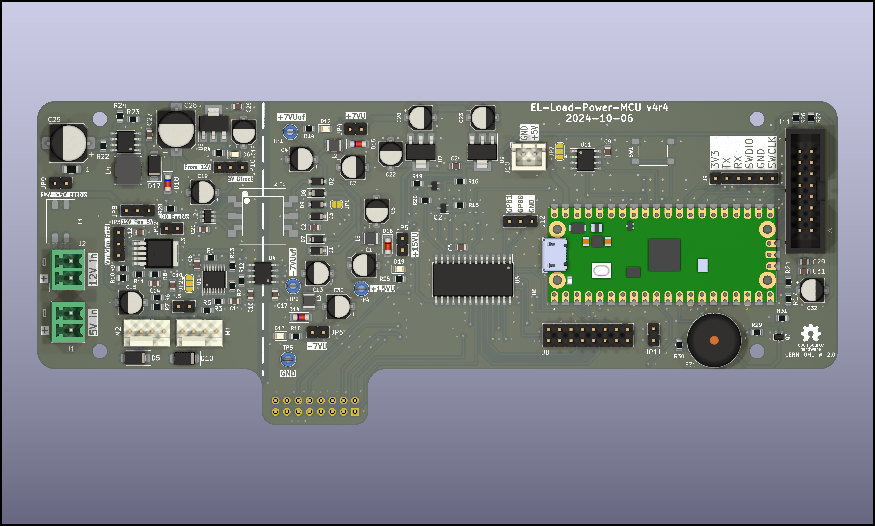
PCB for stand alone deployment outside of BB3. This board contains an isolated power supply (input 5V) with fan controllers, MCU, GPIO and a bunch of connectors. It directly fits to the Analog PCB with an addidional IDC cable. There is also an IDC connector to the Front panel PCB.

EL-Load-Power-MCU

EL-Load-Panel

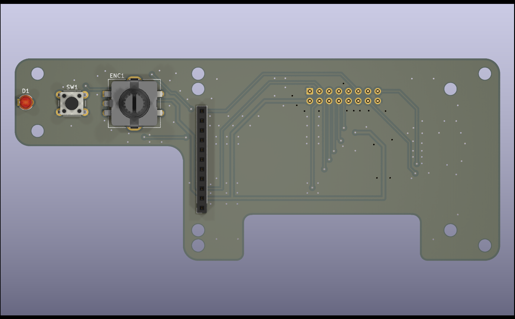
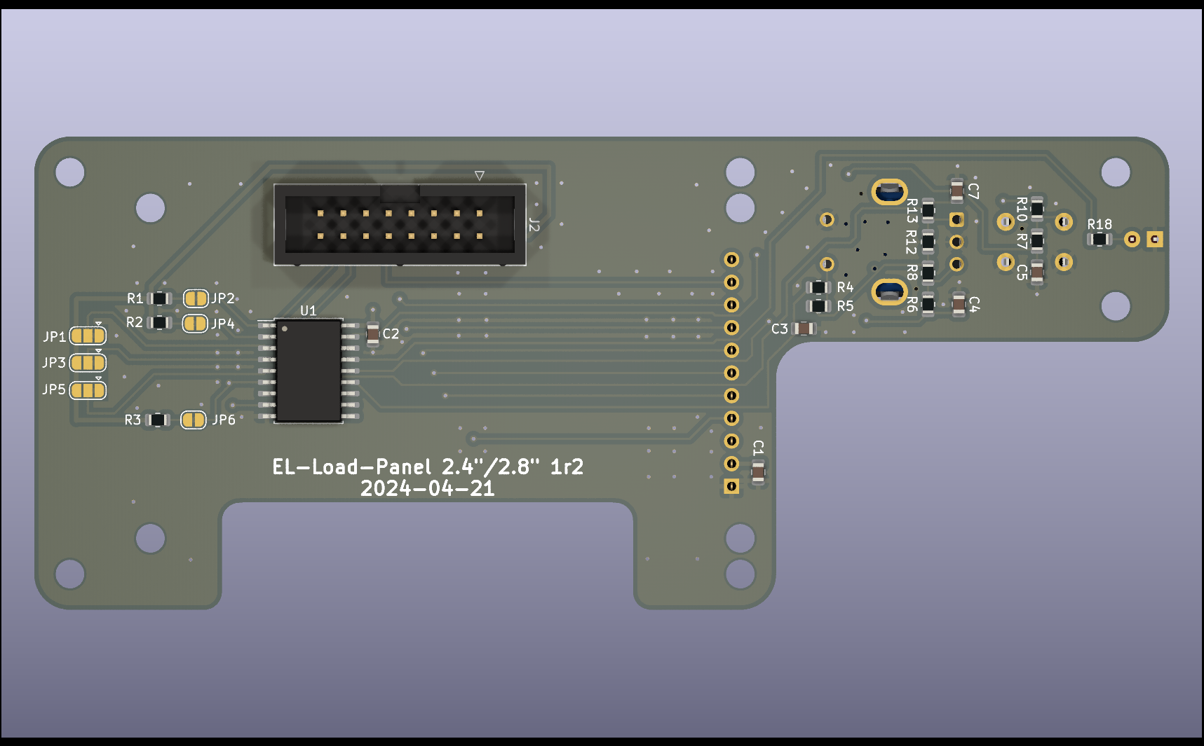
Front panel PCB for standalone deployment. Connects to EL-Load-Power-MCU. Has a connector for common 2.4/2.8" TFT touchscreen PCBs, 1 encoder, 1 microswitch and one 1 LED.

EL-Load-Panel EL-Load-Panel backside

Obsolete PCB's

EL-Load-Simple-Power

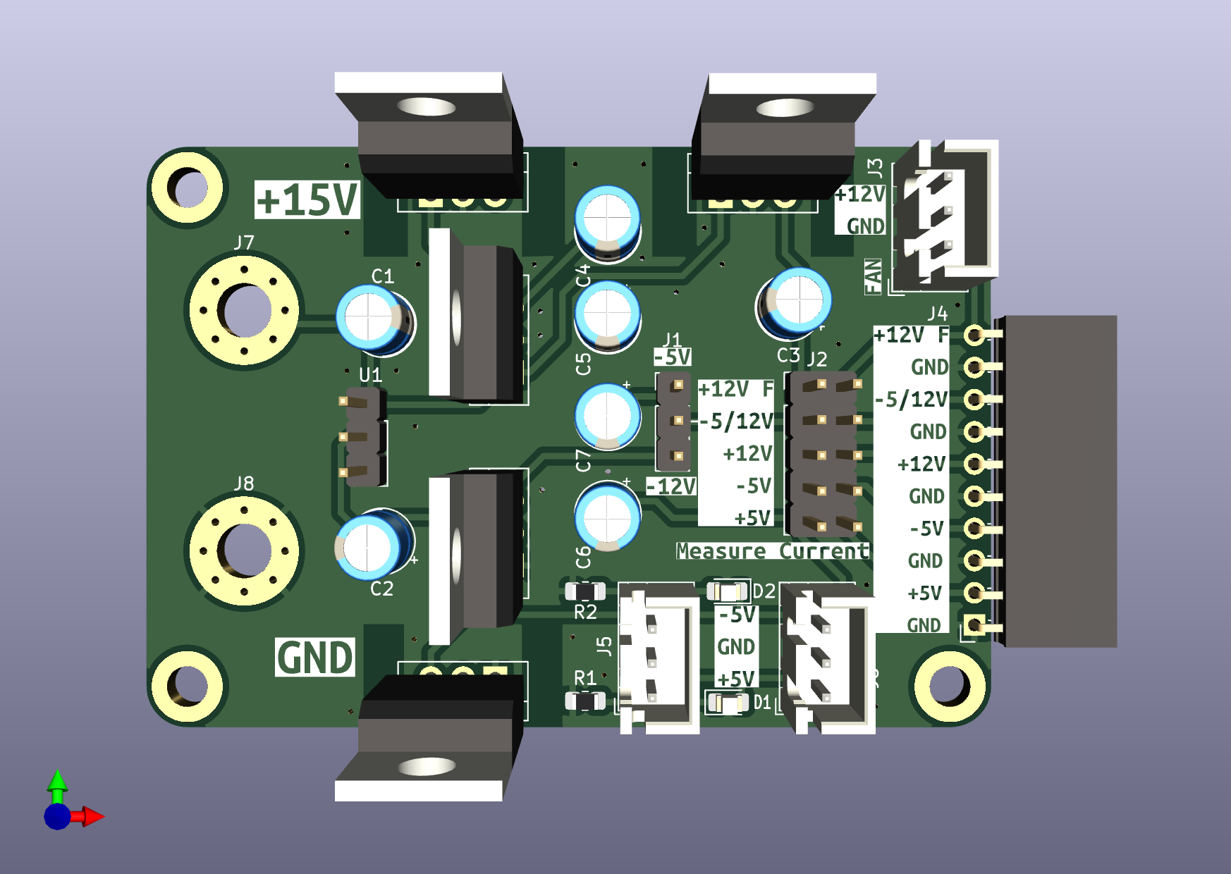
Obsolete test board. Very simple 78*/79* based power supply to generate 2x+12V, 1x+5V, 1x-5V and optionally -12V. Was used for previous version of EL-Load-Analog.

EL-Load-Simple-Power

EL-Load-Fan-Controller

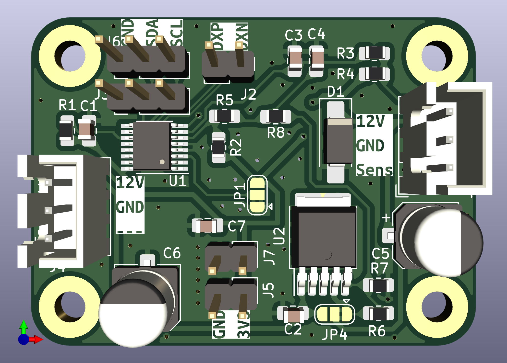
Obsolete test board for the fan controller. For testing MAX31760 with 12V LDO regulation. Not used anymore. MAX31760 is now on Power-MCU-board.

EL-Load-Fan-Controller

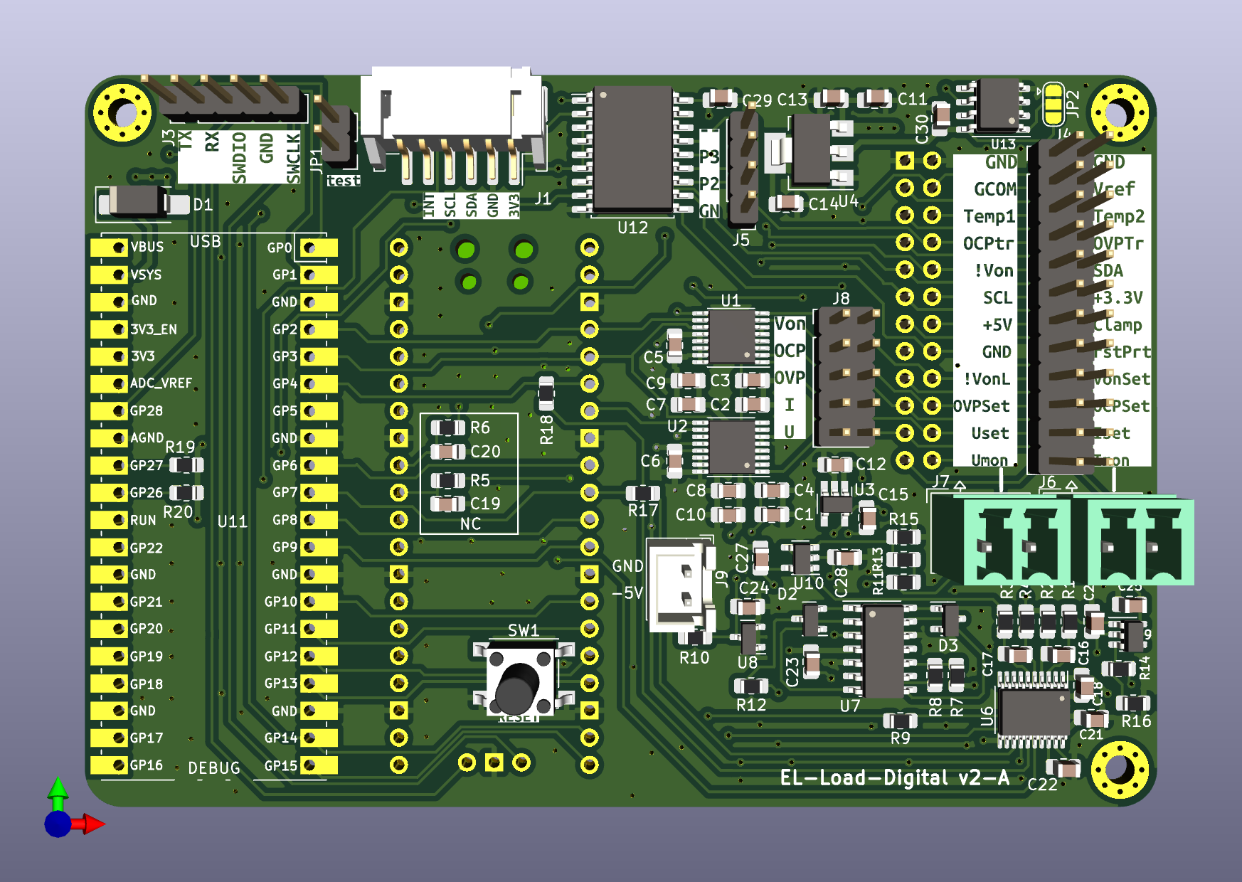
EL-Load-Digital

Obsolete test board for the MCU + ADC + DAC + GPIO + Touchscreen connection. DAC + ADC's are now on analog board. MCU and GPIO are now on new Power-MCU-board.

EL-Load-Digital

Ownership and License

This work is licensed under multiple licences:

  • All hardware designs are licensed under CERN-OHL-W-2.0
  • All original software source code is licensed under GPL-3.0-or-later.
  • All documentation is licensed under CC-BY-SA-4.0.
  • There are also parts imported from other sources. See the indivdual files for there specific licenses.

Parts

344
QtyValueFootprintReferences
50100nCapacitor_SMD:C_0805_2012MetricC13, C21, C22, C201, C202, C203, C204, C205, C206, C207, C208, C215, C216, C217, C218, C219 +34
20100k 0.1%Resistor_SMD:R_0805_2012MetricR26, R29, R30, R31, R211, R212, R213, R214, R231, R232, R233, R234, R309, R310, R311, R312 +4
1410kResistor_SMD:R_0805_2012MetricR13, R14, R15, R17, R46, R55, R56, R57, R201, R202, R403, R502, R507, R509
111N4148Diode_SMD:D_MiniMELFD2, D3, D9, D10, D11, D12, D13, D14, D15, D301, D302
101uCapacitor_SMD:C_0805_2012MetricC10, C12, C19, C20, C29, C32, C42, C44, C47, C503
10TZMB16-GS08Diode_SMD:D_MiniMELFD7, D8, D201, D202, D204, D205, D206, D207, D208, D209
910nCapacitor_SMD:C_0805_2012MetricC5, C6, C18, C40, C41, C43, C48, C54, C405
80Resistor_SMD:R_0805_2012MetricR11, R12, R23, R24, R25, R45, R221, R222
81k1 0.1%Resistor_SMD:R_0805_2012MetricR215, R216, R217, R218, R235, R236, R237, R238
7100kResistor_SMD:R_0805_2012MetricR1, R16, R20, R50, R53, R54, R321
71MResistor_SMD:R_0805_2012MetricR49, R51, R52, R209, R210, R229, R230
71kResistor_SMD:R_0805_2012MetricR32, R33, R34, R35, R322, R401, R402
722kResistor_SMD:R_0805_2012MetricR39, R42, R58, R203, R205, R223, R225
72N7002Package_TO_SOT_SMD:SOT-23Q1, Q2, Q201, Q202, Q205, Q206, Q301
72kResistor_SMD:R_0805_2012MetricR301, R302, R303, R304, R325, R404, R405
61nCapacitor_SMD:C_0805_2012MetricC1, C213, C214, C227, C228, C310
510uCapacitor_SMD:C_0805_2012MetricC27, C28, C49, C50, C52
4100Resistor_SMD:R_0805_2012MetricR207, R208, R227, R228
410k 0.1%Resistor_SMD:R_0805_2012MetricR27, R28, R305, R306
410mResistor_SMD:R_2512_6332Metric_Pad1.40x3.35mm_HandSolderR219, R220, R239, R240
420k 0.1%Resistor_SMD:R_0805_2012MetricR204, R206, R224, R226
4470pCapacitor_SMD:C_0805_2012MetricC211, C212, C225, C226
44n7Capacitor_SMD:C_0805_2012MetricC209, C210, C223, C224
4IRFP250MPackage_TO_SOT_THT:TO-247-3_VerticalQ203, Q204, Q207, Q208
4LM318DPackage_SO:SOIC-8_3.9x4.9mm_P1.27mmU201, U202, U205, U206
4MCP6V51/LTC2050HVPackage_TO_SOT_SMD:SOT-23-5U203, U204, U207, U208
4MountingHoleMountingHole:MountingHole_3.2mm_M3_DIN965H101, H102, H103, H104
4PESD3V3L1BAFDiode_SMD:D_SOD-323D1, D4, D5, D6
322uCapacitor_SMD:C_0805_2012MetricC11, C51, C53
32u2Capacitor_SMD:C_0805_2012MetricC34, C35, C316
347Resistor_SMD:R_0805_2012MetricR36, R37, R38
34k7Resistor_SMD:R_0805_2012MetricR44, R47, R48
35k 0.1%Resistor_SMD:R_0805_2012MetricR3, R6, R315
3LM393APackage_SO:SOIC-8_3.9x4.9mm_P1.27mmU2, U306, U402
215kResistor_SMD:R_0805_2012MetricR323, R503
21k 0.1%Resistor_SMD:R_0805_2012MetricR307, R308
2330Resistor_SMD:R_0805_2012MetricR8, R21
239k 0.1%Resistor_SMD:R_0805_2012MetricR317, R318
2470Resistor_SMD:R_0805_2012MetricR18, R19
247kResistor_SMD:R_0805_2012MetricR22, R43
274HCT02Package_SO:SO-14_3.9x8.65mm_P1.27mmU305, U403
2750Resistor_SMD:R_0805_2012MetricR9, R10
2DAC8555Package_SO:TSSOP-16_4.4x5mm_P0.65mmU11, U12
2LM833Package_SO:SOIC-8_3.9x4.9mm_P1.27mmU301, U302
2MCP6V51Package_TO_SOT_SMD:SOT-23-5U18, U19
2MMBT5401Package_TO_SOT_SMD:SOT-23Q5, Q8
2MMBT5551Package_TO_SOT_SMD:SOT-23Q3, Q6
2NetTie_2NetTie:NetTie-2_SMD_Pad0.5mmNT201, NT202
2OPA189/MCP6V51/LTC2050HVPackage_TO_SOT_SMD:SOT-23-5U303, U304
2VO1400AEFTRPackage_SO:SO-4_4.4x4.3mm_P2.54mmU8, U9
1+5VTestPoint:TestPoint_Loop_D1.80mm_Drill1.0mm_BeadedTP2
1-1VTestPoint:TestPoint_Pad_1.0x1.0mmTP11
1-2V5TestPoint:TestPoint_Pad_1.0x1.0mmTP9
1-5VTestPoint:TestPoint_Loop_D1.80mm_Drill1.0mm_BeadedTP1
11.5KE100A (smd)Diode_SMD:D_SMCD203
1100nFCapacitor_THT:C_Rect_L18.0mm_W5.0mm_P15.00mm_FKS3_FKP3C3
1100pCapacitor_SMD:C_0805_2012MetricC315
11k5 (3W)Resistor_THT:R_Axial_DIN0516_L15.5mm_D5.0mm_P5.08mm_VerticalR2
11k8Resistor_SMD:R_0805_2012MetricR41
1200Resistor_SMD:R_0805_2012MetricR40
1220Resistor_SMD:R_0805_2012MetricR504
1220nCapacitor_SMD:C_0805_2012MetricC45
124LC32Package_SO:SO-8_3.9x4.9mm_P1.27mmU5
124kResistor_SMD:R_0805_2012MetricR324
12V5TestPoint:TestPoint_Pad_1.0x1.0mmTP12
12k2Resistor_SMD:R_0805_2012MetricR330
133nCapacitor_SMD:C_0805_2012MetricC2
13VTestPoint:TestPoint_Pad_1.0x1.0mmTP10
150k 0.1%Resistor_SMD:R_0805_2012MetricR7
1680nCapacitor_SMD:C_0805_2012MetricC401
17k5Resistor_SMD:R_0805_2012MetricR320
1AD8038Package_SO:SOIC-8_3.9x4.9mm_P1.27mmU401
1ADS131M02Package_SO:TSSOP-20_4.4x6.5mm_P0.65mmU20
1AMS1117Package_TO_SOT_SMD:SOT-223-3_TabPin2U22
1AOSP66923Package_SO:SO-8_3.9x4.9mm_P1.27mmQ7
1CERN-OHL-W-2.0Symbol:OSHW-Logo_7.5x8mm_SilkScreenOSHWLogo1
1Conn_01x02_SocketConnector_Phoenix_MC:PhoenixContact_MC_1,5_2-G-3.81_1x02_P3.81mm_HorizontalJ7
1Conn_02x06_Odd_EvenConnector_PinSocket_2.54mm:PinSocket_2x06_P2.54mm_Vertical_SMDJ3
1Conn_02x08_Odd_EvenConnector_PinSocket_2.54mm:PinSocket_2x08_P2.54mm_Vertical_SMDJ8
1Conn_02x08_Odd_EvenConnector_PinHeader_2.54mm:PinHeader_2x08_P2.54mm_VerticalJ4

The 317 most common of 344 parts.

More from fietser28/EL-Load

6
  • 4 layers179 × 72.5 mmEL Load Power MCU, the printed circuit board in 3D

    EL Load Power MCU

    fietser28/EL-Load

    The DCL8010 electronic load module features a DC Electronic Load with several modes and protections. This project is the for the development boards for this project. There is a seperate git project for the firmware.

    137 parts15
  • 4 layers100 × 68.3 mmEL Load Digital, the printed circuit board in 3D

    EL Load Digital

    fietser28/EL-Load

    The DCL8010 electronic load module features a DC Electronic Load with several modes and protections. This project is the for the development boards for this project. There is a seperate git project for the firmware.

    89 parts15
  • 2 layers49 × 49 mmEL Load Reverse Polarity, the printed circuit board in 3D

    EL Load Reverse Polarity

    fietser28/EL-Load

    The DCL8010 electronic load module features a DC Electronic Load with several modes and protections. This project is the for the development boards for this project. There is a seperate git project for the firmware.

    63 parts15
  • 2 layers127 × 53 mmEL Load Panel, the printed circuit board in 3D

    EL Load Panel

    fietser28/EL-Load

    The DCL8010 electronic load module features a DC Electronic Load with several modes and protections. This project is the for the development boards for this project. There is a seperate git project for the firmware.

    46 parts15
  • 2 layers66.6 × 45.8 mmEL Load Simple Power, the printed circuit board in 3D

    EL Load Simple Power

    fietser28/EL-Load

    The DCL8010 electronic load module features a DC Electronic Load with several modes and protections. This project is the for the development boards for this project. There is a seperate git project for the firmware.

    38 parts15
  • 2 layers46 × 34 mmEL Load Fan Controller, the printed circuit board in 3D

    EL Load Fan Controller

    fietser28/EL-Load

    The DCL8010 electronic load module features a DC Electronic Load with several modes and protections. This project is the for the development boards for this project. There is a seperate git project for the firmware.

    36 parts15

Similar boards

  • 2 layers160 × 100 mmZavrsni rad, the printed circuit board in 3D

    Zavrsni rad

    anniberi/master-thesis

    Master's thesis: device for measuring the series resistance of PV panels. This device uses a MOSFET transistor as a variable load to measure the I-V curve of the PV panel.

    32 parts1
  • 4 layers150 × 99.5 mmRnvm bart, the printed circuit board in 3D

    Rnvm bart

    kitspace-test-repos/kicad6-file-collection

    883 partsMIT
  • 4 layers161 × 100 mmCurrent3x3A Artiq, the printed circuit board in 3D

    Current3x3A Artiq

    KLFAMO/current3x3A_Artiq

    3 channel current driver (up to 3A each channel) compatible with Artiq

    365 parts
  • 2 layers42.5 × 62.5 mmEvse, the printed circuit board in 3D

    Evse

    Tinkerforge/evse-bricklet

    This Bricklet together with the ESP32 Brick the RS485 Bricklet and the NFC Bricklet form the hardware used in the WARP Charger

    92 parts3
  • 2 layers250 × 121 mmPWM Schematic, the printed circuit board in 3D

    PWM Schematic

    Shriniketpk2124/Design-Assembly-and-Commissioning-of-a-GreenPHY-Based-EVSE-Signalling-and-Communication-Emulator

    Mixed-signal EVSE prototype for IEC 61851 control-pilot signalling, Green PHY/SLAC, and ISO 15118-2 communication experiments.

    109 parts
  • 2 layers115.8 × 98.6 mmEe115-capstone, the printed circuit board in 3D

    Ee115-capstone

    tsaimatthew/ee115-capstone

    191 parts

Questions

How big is the EL Load Analog PCB?

It measures 185 × 95 mm and has 4 copper layers, 1.57 mm thick.

What parts does the EL Load Analog use?

344 parts, built around the MCP6V51-E/OT, LM318D, DAC8555IPW and AD8038AR. The full list of its parts is on this page, with links to each part's symbol and footprint where PCBKit's library has them.

Where can I download the EL Load Analog KiCad files?

From the fietser28/EL-Load repository on GitHub, at the commit this page was made from: the board is EL-Load-Analog/EL-Load-Analog.kicad_pcb and its schematic EL-Load-Analog/DIB.kicad_sch. PCBKit opens the board in the browser, with nothing to install.

Can I use the EL Load Analog design in my own project?

Its repository states no licence, so its author keeps all rights: ask fietser28 before reusing the design.