Master's thesis: device for measuring the series resistance of PV panels. This device uses a MOSFET transistor as a variable load to measure the I-V curve of the PV panel. A custom PCB is developed, Arduino firmware and Python I-V curve fitting using the single-diode equation.
Zavrsni rad is an open-source printed circuit board by anniberi, from the anniberi/master-thesis repository on GitHub. It is a 2-layer board of 160 × 100 mm with 32 parts on 41 nets, routed with 115 tracks and 0 vias.
It is built around the ARDUINO UNO R3, LM358 and IRFP250MPBF. Its parts include 11 connectors, 8 resistors, 2 ICs and 1 transistor. It belongs with the power boards and the AVR (ATmega, ATtiny) boards of this library.
Device for Measuring the Series Resistance of PV Panels
Master's thesis project covering the full development of a low-cost device that measures the series resistance of photovoltaic panels: from the single-diode model and simulation, through two prototypes, to a home-etched final PCB tested in the field. An IRFP250M MOSFET acts as an electronically controlled variable load that sweeps the panel's I-V curve in milliseconds. An Arduino UNO drives it through an MCP4921 DAC and an op-amp control loop and reads voltage and current with an ADS1115 ADC. A Python Nelder-Mead fit of the single-diode model then estimates the series resistance, and a field comparison of three op-amps (LM358, NE5532, MCP6022) identifies the MCP6022 as the most reliable choice.
Note: Apart from this summary, everything in this project is written in Bosnian: the rest of this README, the source code, the comments and the technical documentation.
Napomena: Izvorni kod, komentari i tehnička dokumentacija za ovaj projekat su napisani na bosanskom jeziku.
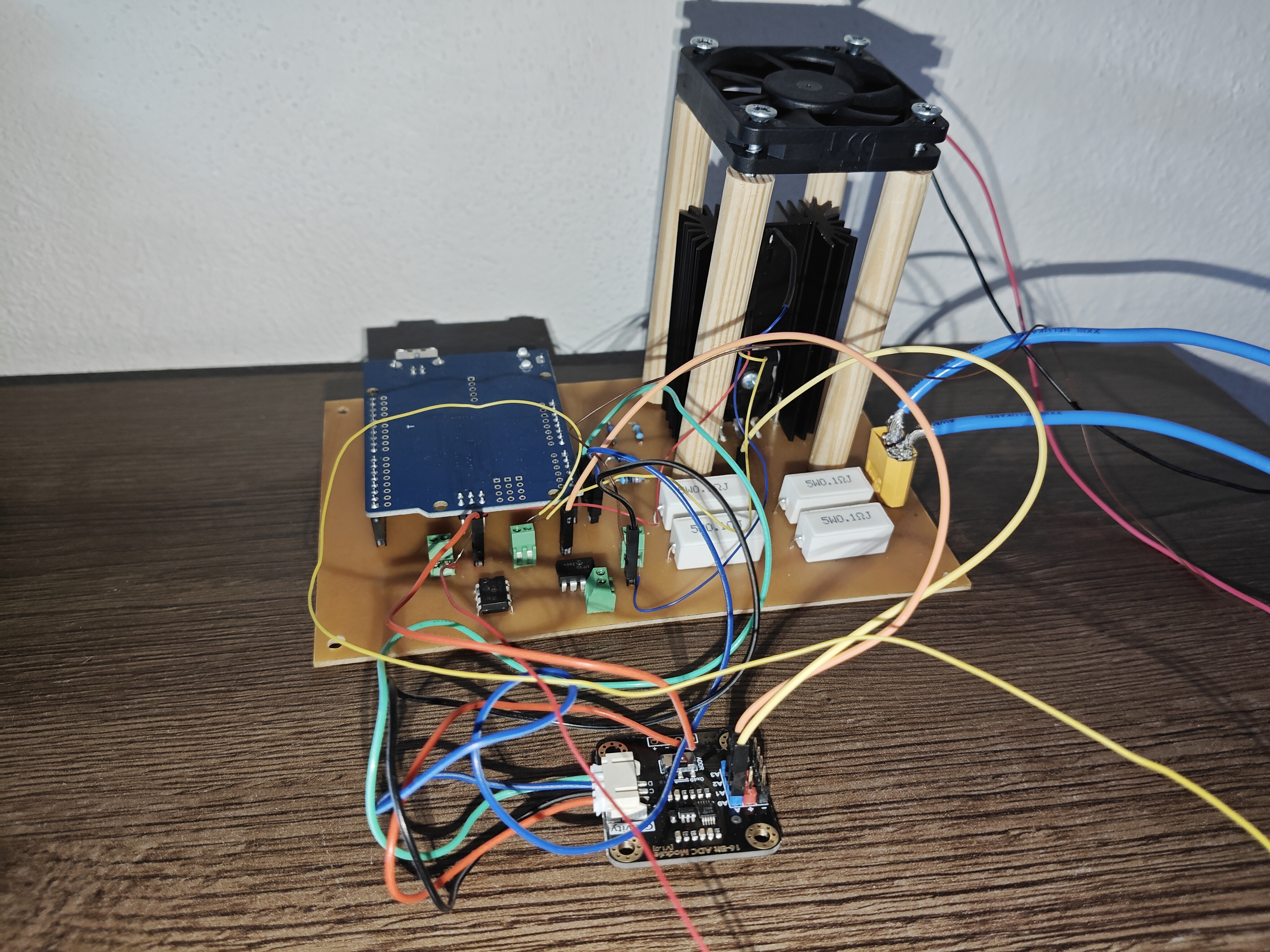
Slika 1: Izrađeni finalni uređaj
O projektu
Završni rad drugog ciklusa studija „Razvoj uređaja za mjerenje serijskog otpora PV panela", izrađen na Odsjeku za automatiku i elektroniku Elektrotehničkog fakulteta Univerziteta u Sarajevu (septembar 2026. godine).
Serijski otpor fotonaponskog (PV) panela važan je pokazatelj stanja panela. Koristi se za dijagnostiku, praćenje degradacije tokom dugogodišnjeg rada i nadzor solarnih elektrana. Pošto je serijski otpor veoma male vrijednosti (manje od 1 Ω), ne može se izmjeriti standardnim metodama. Zato uređaj snima parove struja-napon, formira I-V krivu panela i iz nje, korištenjem jednodiodnog modela, estimira parametre panela, među kojima je i serijski otpor.
Ključni rezultati
Algoritam estimacije verificiran je na podacima proizvođača za panel CHSM6610P-250: Rs = 0,218 Ω pri STC i Rs = 0,247 Ω pri NOCT uslovima.
Terenski testovi pokazali su da izbor operacionog pojačala presudno utiče na kvalitet snimljene I-V krive.
Najbolje rezultate dalo je operaciono pojačalo MCP6022. Iz krive od 100 tačaka estimirano je Rs = 0,409 Ω, a estimacije iz podskupova od 4 do 10 tačaka iste krive odstupaju od te vrijednosti između 5,4 % i 24,2 %.
Ograničenje: MCP6022 je napajano naponom od 12 V, što je iznad dozvoljenog po specifikaciji proizvođača. Tako je osigurano potpuno otvaranje kanala tranzistora, ali se dugotrajan pouzdan rad uređaja ne može garantovati. Pored toga, ne postoji stvarna referentna vrijednost serijskog otpora Rs u odnosu na koju se mogu verificirati dobiveni terenski rezultati.
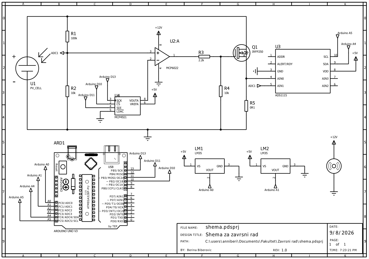
DA konvertor MCP4921 (12-bitni) zadaje referentni napon na "-" ulazu operacionog pojačala. Na "+" ulazu operacionog pojačala je napon sa naponskog djeljitelja koji je skalirani napon sa izlaza solarnog panela.
Operaciono pojačalo upravlja gate-om MOSFET tranzistora IRFP250M. Tranzistor se ponaša kao elektronski promjenljivi otpornik na izlazu panela i postavlja radnu tačku panela. Ako je napon na gate-u tranzistora visok, drain-source struja je veća (a samim tim i struja na izlazu panela), dakle napon na izlazu panela je manji i time smo dobili inverziju početnog napona postavljenog preko DA konvertora tako da je uspostavljena negativna povratna sprega u krugu. Suprotna stvar se desi ako je napon na gate-u tranzistora nizak, tako da opet je uspostavljena negativna povratna sprega unutar kruga i u tom slučaju.
AD konvertor ADS1115 (16-bitni) mjeri napon na naponskom djeljitelju (napon panela) i napon na shunt otporniku (struja panela).
Svaka tačka mjeri se u kratkom impulsu (reda 10 ms) kako bi tranzistor ostao unutar sigurne radne oblasti (SOA). Temperatura panela i hladnjaka tranzistora prati se LM35 senzorima. Sva komunikacija sa DAC-om, ADC-om i senzorima se vrši preko Arduino UNO mikrokontrolera.
Python skripta na laptopu pokreće mjerenje, prikuplja tačke i Nelder-Mead optimizacijom prilagođava jednodiodni model izmjerenoj I-V krivoj.
Struktura repozitorija
Direktorij
Opis
Rad/
LaTeX izvorni kod završnog rada, slike i finalni PDF (Zavrsni_rad_MoE_Berina_Biberovic.pdf)
Prezentacija/
Prezentacija za odbranu (Beamer, tema metropolis) i finalni PDF
IV kriva datasheet/
Estimacija parametara jednodiodnog modela iz podataka proizvođača i skripte za grafike iz teorijskog dijela rada (Prilog A rada)
Fitovanje krive/
Estimacija parametara iz ručno i automatski snimljenih I-V krivih (Prilog B rada), uz mjerenja i rezultate
Simulacija sheme/
Simulacija baznog sklopa u alatu Proteus Design Suite
Sheme/
Proteus sheme prototipa A i finalnog uređaja
Komponente/
Proteus modeli pojedinih komponenti (ADS1115, solarni panel)
Prototip A/
Arduino kod, Python skripte i rezultati laboratorijskih testova prototipa A (verzije 1 i 2)
Testiranje panela/
Svih 20 terenskih testova prototipa B i finalnog uređaja: Arduino firmver, Python skripte, sirova mjerenja i grafici
Rezultati/
Odabrani rezultati za rad, razvrstani po operacionom pojačalu (LM358, NE5532, MCP6022)
PCB/
KiCad projekat finalnog uređaja (shema, PCB, vlastiti footprint hladnjaka, izvozi u PDF/SVG i 3D prikazi)
Terenski testovi
Svaki direktorij u Testiranje panela/ sadrži firmver (.ino), Python skriptu za upravljanje mjerenjem i obradu, te sirove podatke i grafike tog testa. Nazivi direktorija ukratko opisuju svrhu testa (npr. ciljanje MPP-a, hardkodirani DAC kodovi, sidro, 100 tačaka). U samom radu detaljno su analizirani testovi 6, 13, 15, 19 i 20.
Finalno mjerenje s MCP6022 operacionim pojačalom nalazi se u direktoriju Testiranje panela/Test 20 (kao 18 ali za 6022)/:
iv_komplet/iv_komplet.ino: firmver koji snima 100 tačaka od napona otvorenog kola Voc do 0 V;
iv_komplet.py: skripta koja pokreće mjerenje, prilagođava model svim tačkama (referentni Rs) i podskupovima od 4 do 10 tačaka, te računa relativne greške.
Pokretanje
Python skripte
Preduslovi: Python 3 s paketima numpy, scipy, matplotlib i pyserial.
Primjer, estimacija parametara iz podataka proizvođača:
bash
cd "IV kriva datasheet"
python3 main.py
Skripte koje komuniciraju s uređajem koriste serijski port zadan na početku skripte (npr. PORT = "/dev/ttyACM0", 115200 bauda). Port je potrebno prilagoditi vlastitom sistemu.
Arduino firmver
Preduslovi: Arduino IDE i biblioteka Adafruit ADS1X15 (instalira se preko Library Manager-a).
Otvoriti željenu .ino datoteku (npr. Testiranje panela/Test 20 (kao 18 ali za 6022)/iv_komplet/iv_komplet.ino).
Izabrati ploču Arduino UNO i odgovarajući port, pa učitati firmver.
Povezivanje (prema komentaru u firmveru):
ADS1115 preko I2C (adresa 0x48, A4/A5);
MCP4921 preko SPI (CS: D10, SCK: D13, SDI: D11);
LM35 senzor panela na A0 i LM35 senzor hladnjaka na A1.
Mjerenje se pokreće slanjem komande S preko serijske veze, što Python skripta radi automatski.
Završni rad i prezentacija
Rad se prevodi standardnom LaTeX distribucijom (TeX Live ili MiKTeX) uz BibTeX:
bash
cd Rad
pdflatex Zavrsni_rad_MoE_Berina_Biberovic.tex
bibtex Zavrsni_rad_MoE_Berina_Biberovic
pdflatex Zavrsni_rad_MoE_Berina_Biberovic.tex
pdflatex Zavrsni_rad_MoE_Berina_Biberovic.tex
Prezentacija koristi Beamer temu metropolis:
bash
cd Prezentacija
pdflatex prezentacija.tex
Sheme i PCB
Proteus projekti (.pdsprj) otvaraju se u alatu Proteus Design Suite.
KiCad projekat otvara se preko PCB/zavrsni_rad/zavrsni_rad.kicad_pro (KiCad 9 ili noviji). Vlastita biblioteka simbola i footprint hladnjaka povezani su relativnim putanjama unutar projekta.
Metodologija
Teorijska osnova: fotonaponski efekat, jednodiodni model PV panela, I-V i P-V karakteristike te uticaj serijske i paralelne otpornosti.
Softverski model: implementacija estimacije parametara jednodiodnog modela u Pythonu (Nelder-Mead optimizacija), verifikacija na podacima proizvođača te na I-V krivim snimljenim ručno pomoću otporne dekade.
Razvoj uređaja:
izbor promjenljivog otpora i komponenti (tranzistor, AD i DA konvertor, operaciono pojačalo, shunt otpornik, temperaturni senzori, mikrokontroler, napajanje);
simulacija u Proteusu;
laboratorijski prototip A na matador ploči;
prototip B za terenska mjerenja.
Finalni uređaj:
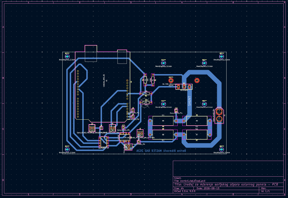
PCB dizajniran u KiCadu prema standardu IPC-2221 (vodovi za struje do oko 8,5 A);
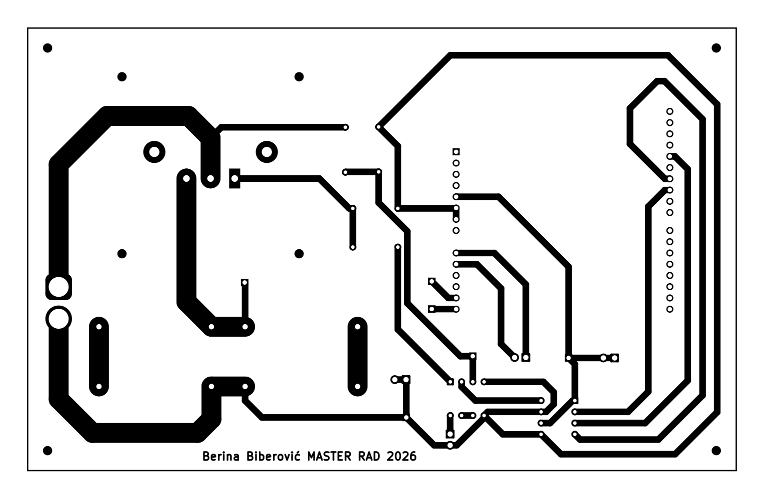
pločica izrađena kućnim fotolitografskim postupkom: razvijanje u natrij-hidroksidu, etching rađen sa natrij-persulfatom;
terenska komparacija operacionih pojačala LM358, NE5532 i MCP6022.
Slika 3: PCB layout (KiCad)
Slika 4: Maska za PCB pločicu korištena prilikom kućnog etching-a
Autor
Student: Berina Biberović
Mentor: red. prof. dr Abdulah Akšamović
Ustanova: Elektrotehnički fakultet, Univerzitet u Sarajevu, Odsjek za automatiku i elektroniku
The DCL8010 electronic load module features a DC Electronic Load with several modes and protections. This project is the for the development boards for this project. There is a seperate git project for the firmware.
A learning project to create an EV AC Charging station based on an Arduino Uno
32 parts50
Questions
How big is the Zavrsni rad PCB?
It measures 160 × 100 mm and has 2 copper layers, 1.6 mm thick.
What parts does the Zavrsni rad use?
32 parts, built around the ARDUINO UNO R3, LM358 and IRFP250MPBF. The full list of its parts is on this page, with links to each part's symbol and footprint where PCBKit's library has them.
Where can I download the Zavrsni rad KiCad files?
From the anniberi/master-thesis repository on GitHub, at the commit this page was made from: the board is PCB/zavrsni_rad/zavrsni_rad.kicad_pcb and its schematic PCB/zavrsni_rad/zavrsni_rad.kicad_sch. PCBKit opens the board in the browser, with nothing to install.
Can I use the Zavrsni rad design in my own project?
Its repository states no licence, so its author keeps all rights: ask anniberi before reusing the design.