4 layers24 × 45 mm
Radianite uFM
RadianiteComputers/RadianiteBoards
A collection of Radianite boards we have designed so far. All are licensed under CC BY-SA 4.0
68 parts

 fehlfarbe/ESP32-Alarm-clock1
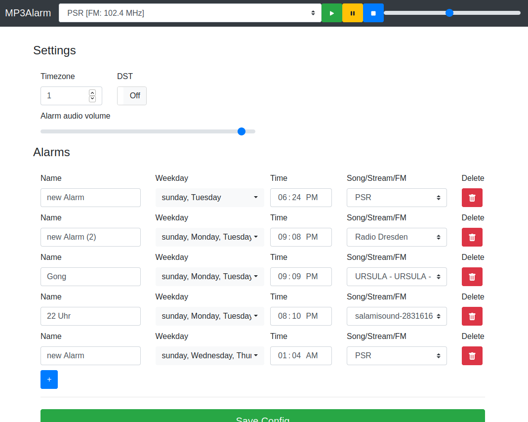
This is an ESP32 based alarm clock that plays mp3 files from SD, webstreams or even FM radio. You can configure multiple alarms and add new songs to your sd card with a simple webinterface.
Mp3alarm is an open-source printed circuit board by fehlfarbe, from the fehlfarbe/ESP32-Alarm-clock repository on GitHub, published under the MIT licence. It is a 2-layer board of 67 × 54 mm with 69 parts on 69 nets, routed with 450 tracks and 153 vias.
It is built around the ESP32-S3-WROOM-1-N8, RDA5807FP and TM1637, with the AMS1117-3.3, UDA1334ATS/N2 and WS2812B among its other parts. Its parts include 22 resistors, 19 capacitors, 11 connectors, 4 ICs and 4 diodes. It belongs with the ESP32 boards of this library.


This is an ESP32 based alarm clock that plays mp3 files from SD, webstreams or even FM radio. You can configure multiple alarms and add new songs to your sd card with a simple webinterface.
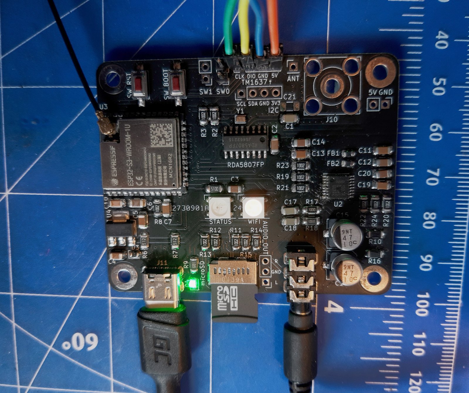
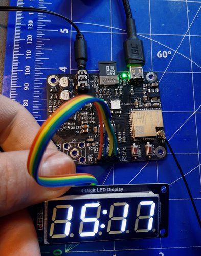
Photos of the current PCB version (without assembled radio antenna connector J10):
The KiCAD project and gerber files are available at hardware/pcb/
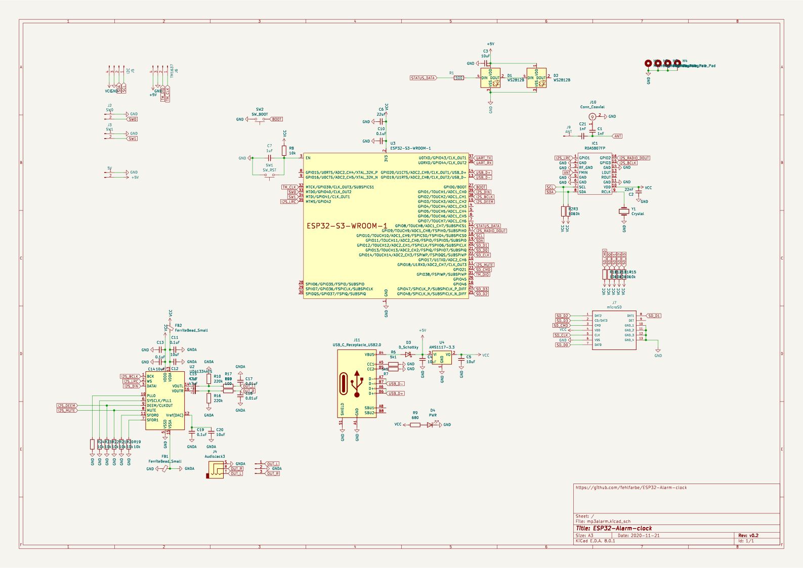
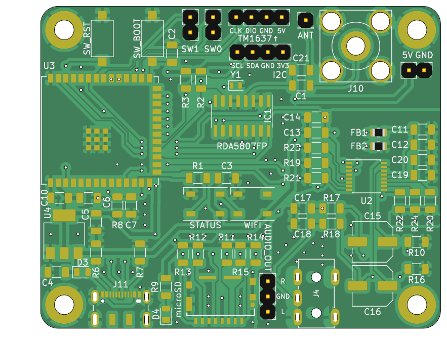
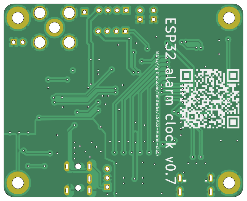
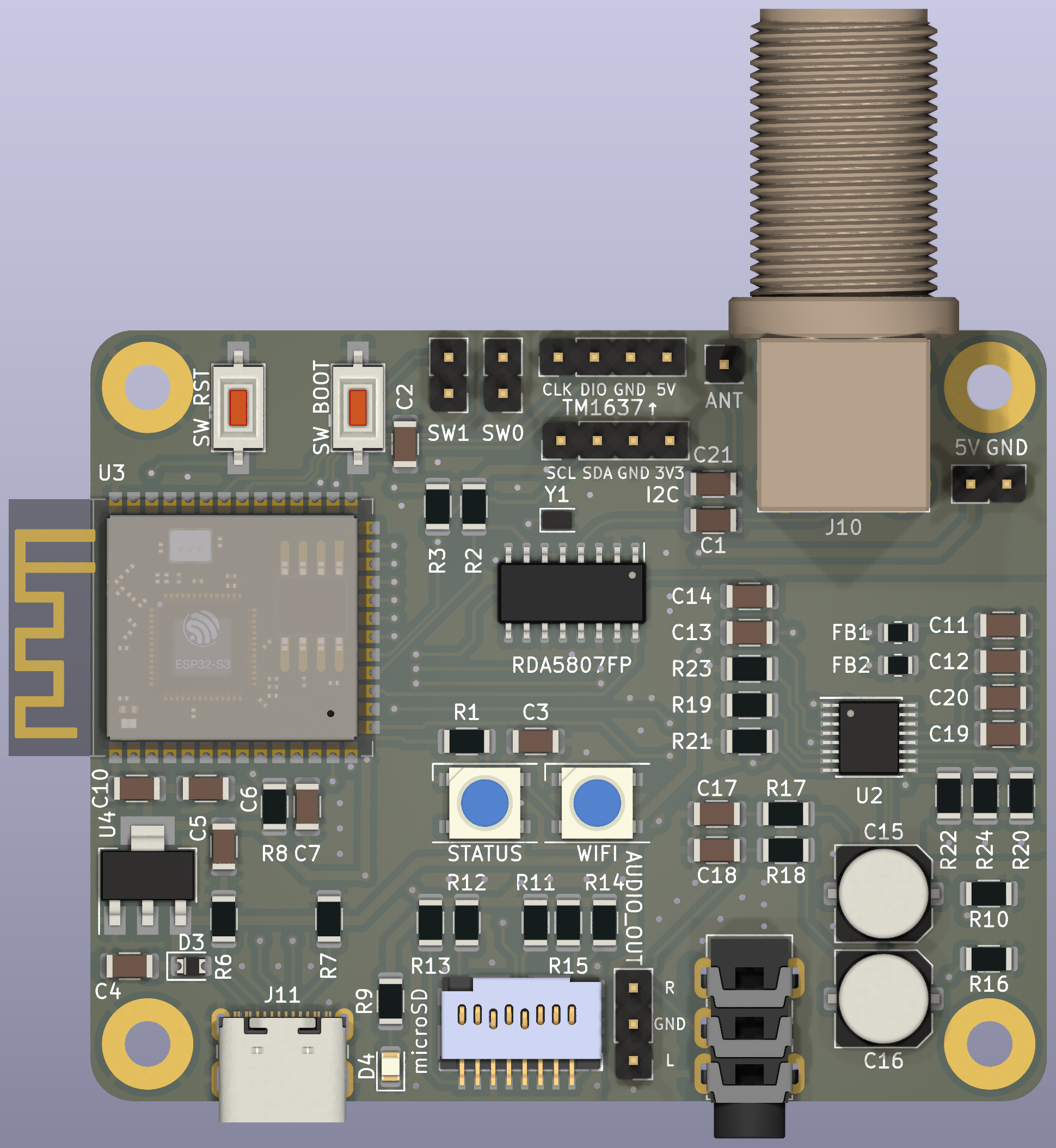
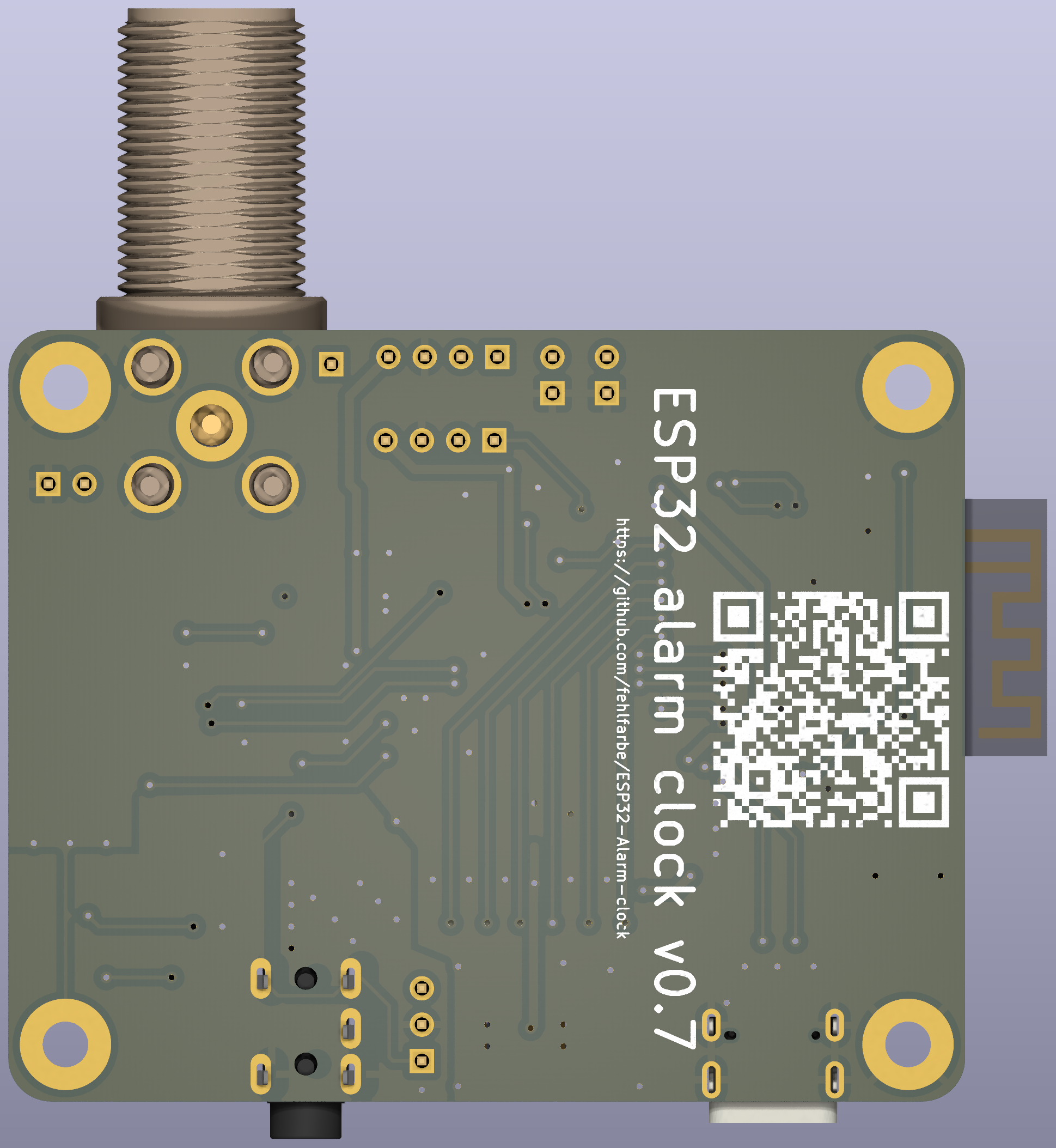
hardware/pcb/export/BOM.xml
Just clone the project and open it in platformIO. PIO will download all necessary libs. Connect the ESP32 on your USB port an click "Upload" in PIO. After this open a terminal in PIO and run pio run -t uploadfs to upload the webinterface to ESP32's flash.
The ESP32 will reboot and opens an accesspoint where you can connect to your WiFi. The clock is synced over the internet via NTP.
| Qty | Value | Footprint | References |
|---|---|---|---|
| 14 | 10k | Resistor_SMD:R_1206_3216Metric | R2, R3, R8, R11, R12, R13, R14, R15, R19, R20, R21, R22, R23, R24 |
| 6 | 10uF | Capacitor_SMD:C_1206_3216Metric | C3, C4, C5, C12, C14, C20 |
| 4 | 0.1uF | Capacitor_SMD:C_1206_3216Metric | C10, C11, C13, C19 |
| 4 | MountingHole_Pad | MountingHole:MountingHole_3.2mm_M3_Pad | H1, H2, H3, H4 |
| 2 | 0.01uF | Capacitor_SMD:C_1206_3216Metric | C17, C18 |
| 2 | 100 | Resistor_SMD:R_1206_3216Metric | R17, R18 |
| 2 | 1nF | Capacitor_SMD:C_1206_3216Metric | C1, C21 |
| 2 | 220k | Resistor_SMD:R_1206_3216Metric | R10, R16 |
| 2 | 47uF | Capacitor_SMD:C_Elec_6.3x5.4 | C15, C16 |
| 2 | 5k1 | Resistor_SMD:R_1206_3216Metric | R6, R7 |
| 2 | FerriteBead_Small | Resistor_SMD:R_0805_2012Metric | FB1, FB2 |
| 2 | WS2812B | LED_SMD:LED_WS2812B_PLCC4_5.0x5.0mm_P3.2mm | D1, D2 |
| 1 | 1uF | Capacitor_SMD:C_1206_3216Metric | C7 |
| 1 | 22nF | Capacitor_SMD:C_1206_3216Metric | C2 |
| 1 | 22uF | Capacitor_SMD:C_1206_3216Metric | C6 |
| 1 | 500 | Resistor_SMD:R_1206_3216Metric | R1 |
| 1 | 5V | Connector_PinHeader_2.54mm:PinHeader_1x02_P2.54mm_Vertical | J8 |
| 1 | 680 | Resistor_SMD:R_1206_3216Metric | R9 |
| 1 | AMS1117-3.3 | Package_TO_SOT_SMD:SOT-223-3_TabPin2 | U4 |
| 1 | ANT | Connector_PinHeader_2.54mm:PinHeader_1x01_P2.54mm_Vertical | J9 |
| 1 | AUDIO | Connector_PinHeader_2.54mm:PinHeader_1x03_P2.54mm_Vertical | J1 |
| 1 | AudioJack3 | footprints:PJ-313 | J4 |
| 1 | Conn_Coaxial | Connector:F_Sat_Connector | J10 |
| 1 | Crystal | Crystal:Crystal_SMD_2012-2Pin_2.0x1.2mm | Y1 |
| 1 | D_Schottky | Diode_SMD:D_0805_2012Metric | D3 |
| 1 | ESP32-S3-WROOM-1 | PCM_Espressif:ESP32-S3-WROOM-1 | U3 |
| 1 | I2C | Connector_PinHeader_2.54mm:PinHeader_1x04_P2.54mm_Vertical | J5 |
| 1 | PWR | LED_SMD:LED_0805_2012Metric | D4 |
| 1 | RDA5807FP | Package_SO:SOP-16_3.9x9.9mm_P1.27mm | IC1 |
| 1 | SW0 | Connector_PinHeader_2.54mm:PinHeader_1x02_P2.54mm_Vertical | J2 |
| 1 | SW1 | Connector_PinHeader_2.54mm:PinHeader_1x02_P2.54mm_Vertical | J3 |
| 1 | SW_BOOT | Button_Switch_SMD:SW_SPST_CK_RS282G05A3 | SW2 |
| 1 | SW_RST | Button_Switch_SMD:SW_SPST_CK_RS282G05A3 | SW1 |
| 1 | TM1637 | Connector_PinHeader_2.54mm:PinHeader_1x04_P2.54mm_Vertical | J6 |
| 1 | UDA1334ATS | Package_SO:SSOP-16_4.4x5.2mm_P0.65mm | U2 |
| 1 | USB_C_Receptacle_USB2.0 | Connector_USB:USB_C_Receptacle_JAE_DX07S016JA1R1500 | J11 |
| 1 | microSD | pcb:105162-0001 | J7 |
RadianiteComputers/RadianiteBoards
A collection of Radianite boards we have designed so far. All are licensed under CC BY-SA 4.0


It measures 67 × 54 mm and has 2 copper layers, 1.6 mm thick.
69 parts, built around the ESP32-S3-WROOM-1-N8, RDA5807FP, TM1637 and AMS1117-3.3. The full list of its parts is on this page, with links to each part's symbol and footprint where PCBKit's library has them.
From the fehlfarbe/ESP32-Alarm-clock repository on GitHub, at the commit this page was made from: the board is hardware/pcb/mp3alarm.kicad_pcb and its schematic hardware/pcb/mp3alarm.kicad_sch. PCBKit opens the board in the browser, with nothing to install.
Its repository publishes it under the MIT licence: you may reuse it on that licence's terms (keep the author's notice, and for a copyleft licence share your changes alike).