
4 layers50 × 60 mm
PiCCANTE OBD Dongle
Alia5/PiCCANTE
PiCCANTE is a powerful tool for exploring and reversing CAN busses of vehicles, based on Raspberry Pi Pico (any model)
35 parts104GPL-3.0
 feaser/canfdshield1
Arduino shield with 3.3V CAN FD Transceiver for STM32 Nucleo boards
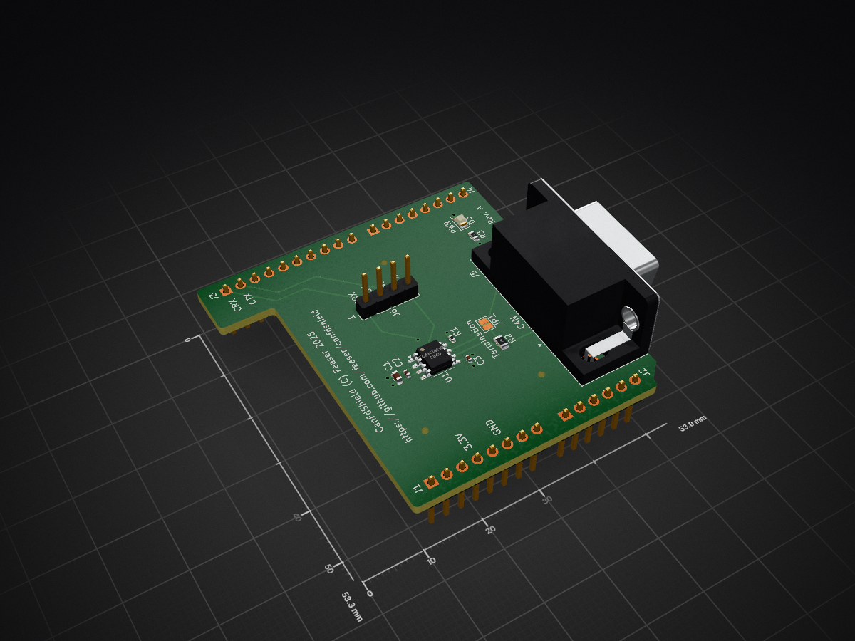
Canfdshield is an open-source printed circuit board by feaser, from the feaser/canfdshield repository on GitHub, published under the MIT licence. It is a 4-layer board of 53.9 × 53.3 mm with 18 parts on 43 nets, routed with 60 tracks and 10 vias.
It is built around the TCAN3413DRB. Its parts include 6 connectors, 3 capacitors, 3 resistors, 1 IC and 1 diode.
 CanFdShield is an expansion board with a CAN FD transceiver, specifically designed for ST Nucleo-64 and Nucleo-144 boards. It features the standard Arduino shield connector layout, making it easy to install this expansion board on your Nucleo board.

With CanFdShield you can connect your ST Nucleo board to a CAN bus. This assumes that the STM32 microcontroller features a CAN or CAN FD controller with CAN-RX on connector pin D15 and CAN-TX on D14.
The Texas Instruments TCAN3413DR CAN FD transceiver was integrated into the design. This 3.3V CAN transceiver works with classical CAN and optimized CAN FD performance at 2, 5, and 8 Mbps.

This board was designed with KiCad and you can find all schematic and PCB design files in the .\hardware directory. You are free to use this design for your own projects.
For testing and verification purposes, the PCB was manufactured and assembled by JLCPCB. It's fully functional. This is what it looks like when installed on a Nucleo-64:

If you would like to order a batch yourself, you can find the Gerber files in .\hardware\gerber. You'll also need the BOM and footprint position files. These are located in .\hardware\assembly.
| Qty | Value | Footprint | References |
|---|---|---|---|
| 2 | 100nF | Capacitor_SMD:C_0402_1005Metric | C2, C3 |
| 1 | 10K | Resistor_SMD:R_0402_1005Metric | R1 |
| 1 | 120 | Resistor_SMD:R_0805_2012Metric | R2 |
| 1 | 4.7uF | Capacitor_SMD:C_0603_1608Metric | C1 |
| 1 | 510 | Resistor_SMD:R_0603_1608Metric | R3 |
| 1 | Analog | Connector_PinHeader_2.54mm:PinHeader_1x06_P2.54mm_Vertical | J2 |
| 1 | CAN XCVR | Connector_PinHeader_2.54mm:PinHeader_1x04_P2.54mm_Vertical | J6 |
| 1 | DSUB9M | Connector_Dsub:DSUB-9_Pins_Horizontal_P2.77x2.84mm_EdgePinOffset7.70mm_Housed_MountingHolesOffset9.12mm | J5 |
| 1 | Digital/PWM | Connector_PinHeader_2.54mm:PinHeader_1x10_P2.54mm_Vertical | J3 |
| 1 | Digital/PWM | Connector_PinHeader_2.54mm:PinHeader_1x08_P2.54mm_Vertical | J4 |
| 1 | Green | LED_SMD:LED_0805_2012Metric | D3 |
| 1 | Power | Connector_PinHeader_2.54mm:PinHeader_1x08_P2.54mm_Vertical | J1 |
| 1 | Rterm | Jumper:SolderJumper-2_P1.3mm_Open_Pad1.0x1.5mm | JP1 |
| 1 | TCAN3413DR | Package_SO:SOIC-8_3.9x4.9mm_P1.27mm | U1 |
The 15 most common of 18 parts.
It measures 53.9 × 53.3 mm and has 4 copper layers, 1.6 mm thick.
18 parts, built around the TCAN3413DRB. The full list of its parts is on this page, with links to each part's symbol and footprint where PCBKit's library has them.
From the feaser/canfdshield repository on GitHub, at the commit this page was made from: the board is hardware/canfdshield.kicad_pcb and its schematic hardware/canfdshield.kicad_sch. PCBKit opens the board in the browser, with nothing to install.
Its repository publishes it under the MIT licence: you may reuse it on that licence's terms (keep the author's notice, and for a copyleft licence share your changes alike).
Alia5/PiCCANTE
PiCCANTE is a powerful tool for exploring and reversing CAN busses of vehicles, based on Raspberry Pi Pico (any model)

AmalRajKC/SylionX
An open source USB to CAN FD adapter for real-time CAN bus monitoring, diagnostics, and frame injection.

lhr-solar/PS-BPSLeader
Reads voltage, temperature, and current of the main battery pack from the Segment Monitoring Board and HV Carrier boards to ensure the battery remains in a safe state.


barkinvar/sugerCANe
A compact interface for three NPN, PNP or logic sensors on an FRC robot. Each port has a removable 5 V / 12 V power jumper; input type is configured in software.


itsTasos/InvictusOne-Flight-Computer
KiCad hardware design for an STM32G474-based flight-data computer for high-power model rockets, with inertial and pressure sensors, CAN-FD, and onboard flash storage.

kquinsland/modular-rack-mount-power-system
Hardware, firmware, and host tooling for a modular mini-rack power system.