4 layers90.2 × 95.9 mm

 itsTasos/InvictusOne-Flight-Computer
KiCad hardware design for an STM32G474-based flight-data computer for high-power model rockets, with inertial and pressure sensors, CAN-FD, and onboard flash storage.
HPR FC G474 3S is an open-source printed circuit board by itsTasos, from the itsTasos/InvictusOne-Flight-Computer repository on GitHub. It is a 4-layer board of 50 × 80 mm with 127 parts on 91 nets, routed with 1,656 tracks and 235 vias.
It is built around the STM32G474RET6, TCAN3413DRB and TPS62902QRYTRQ1, with the ADXL375BCCZ, BMI088 and PESD2CANFD24VT-QR among its other parts. Its parts include 36 resistors, 35 capacitors, 9 ICs, 4 connectors and 2 diodes. It belongs with the sensors and measurement boards and the STM32 boards of this library.


A 4-layer flight-data acquisition and logging board for high-power model rockets. The design combines a 3S LiPo power front end, an STM32G474 microcontroller, multiple flight sensors, non-volatile storage, CAN-FD and UART interfaces, and an external watchdog.
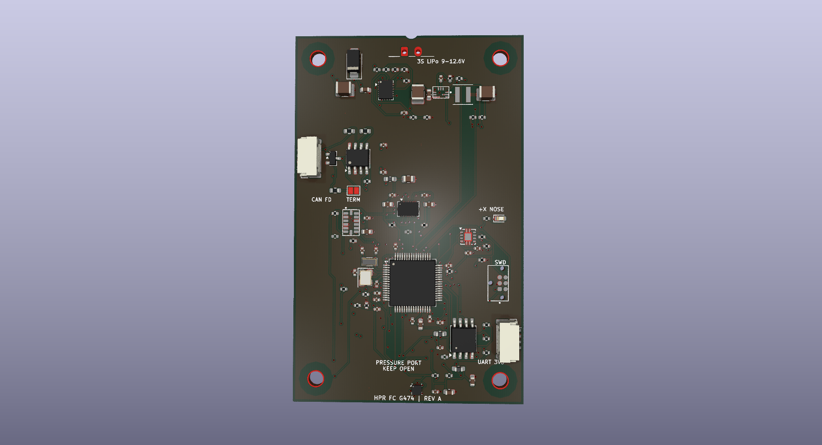
The board is intended to measure, timestamp, store, and communicate flight data. It does not include ignition, pyrotechnic, or recovery-deployment circuitry.
| Item | Design specification |
|---|---|
| Battery input | 3S LiPo, 9.0–12.6 V nominal operating range |
| Battery protection | TPS25940 eFuse; nominal undervoltage rising/falling thresholds of about 8.67 V / 8.14 V, overvoltage cutoff about 13.53 V |
| Input current limit | About 1.74 A, set by the eFuse current-limit resistor |
| Main logic rail | 3.3 V from a TPS62902 synchronous buck converter |
| Sensor rails | 3V3_SENS and 3V3_BARO are ferrite-filtered branches of 3.3 V, not separate regulated outputs |
| Data storage | 128 Mbit / 16 MiB serial NOR flash |
| Communication | CAN-FD, 3.3 V UART, SWD |
| PCB outline | 50 × 80 mm |
| PCB construction | 4 copper layers, nominal 1.6 mm thickness |
| Mounting | Four 3.2 mm non-plated holes on a 40 × 70 mm pattern |
| Test access | 29 bottom-side test points |
Power thresholds and current limit are nominal resistor-based calculations. They are not per-cell LiPo protection thresholds or measured performance limits.
| Reference | Part | Function |
|---|---|---|
| U1 | STM32G474RET6 | Main microcontroller; sensor acquisition, logging control, and communications |
| U2 | TPS3431SQDRBRQ1 | External watchdog; its output can reset the MCU |
| U3 | BMI088 | Accelerometer and gyroscope |
| U4 | ADXL375BCCZ | High-g accelerometer, ±200 g range |
| U5 | LPS22DFTR | Absolute pressure sensor |
| U6 | W25Q128JVSIQ | 128-Mbit serial NOR flash |
| U7 | TCAN3413DR | CAN-FD physical-layer transceiver |
| U8 | TPS25940AQRVCRQ1 | Input eFuse, voltage monitoring, current limiting, and current monitor |
| U9 | TPS62902QRYTRQ1 | Battery-to-3.3 V buck converter |
| U10 | PESD2CANFD24VT-Q | CAN bus transient protection |
| D2 | SMAJ13A-TR | Battery-input TVS diode |
| L1 | XGL4020-102ME, 1 µH | Buck-converter power inductor |
Battery power enters J1 as VBAT_RAW. The input TVS and eFuse feed VBAT_PROTECTED, which supplies the 3.3 V buck converter and is also available at J2 pin 1. The buck output is 3V3_MAIN. Ferrite filters create the 3V3_SENS branch for the inertial sensors, the 3V3_BARO branch for the pressure sensor, and a filtered VDDA branch for the MCU ADC.
The BMI088 uses SPI1, the ADXL375 uses SPI2, the pressure sensor uses I2C3, and the external flash uses SPI3. The MCU connects to the CAN-FD transceiver through FDCAN1, to J3 through USART2, and to a debug probe through SWD at J4. All board domains share a common ground; the sensor supply branches are filtered but not galvanically isolated.
See Hardware design for the power path and design calculations, Connector pinout for connector and test-point details, and Programming and debug for the custom SWD connection.
| Connector | Pin | Signal |
|---|---|---|
| J1 — battery | 1 | VBAT_RAW, battery positive |
| 2 | GND | |
| J2 — CAN module bus | 1 | VBAT_PROTECTED, battery voltage |
| 2 | GND | |
| 3 | CAN_H | |
| 4 | CAN_L | |
| J3 — UART | 1 | 3V3_MAIN |
| 2 | GND | |
| 3 | UART_TX from MCU | |
| 4 | UART_RX to MCU | |
| J4 — SWD | 1 | 3V3_MAIN / target reference |
| 2 | SWDIO | |
| 3 | GND | |
| 4 | SWCLK | |
| 5 | GND | |
| 6 | NRST |
J2 pin 1 carries protected battery voltage, not 3.3 V. J3 is a 3.3 V UART interface, not RS-232. J4 uses a custom six-contact assignment and is not the standard TC2030-CTX pinout. Confirm the pin numbering and cable wiring before connecting external equipment.
The board is 50 × 80 mm. The +X nose direction is marked on the silkscreen along the long board axis. The pressure-sensor port should remain unobstructed when installed. The four mounting holes are non-plated and form a 40 × 70 mm rectangle.
Open hardware/kicad/HPR_FC_G474_3S.kicad_pro in KiCad. The PCB, hierarchical schematic, local libraries, and design-rule file are kept together under hardware/kicad/; the project uses paths relative to that directory.
The board has no battery charger, cell balancer, individual-cell monitor, or guaranteed reverse-polarity protection. The eFuse monitors the pack input as a whole. Its nominal undervoltage threshold is below the safe minimum for some individual 3S LiPo cells, so it must not be used as cell-level protection.
The CAN interface is not galvanically isolated. The input TVS clamp can exceed the eFuse absolute-maximum input voltage under some surge conditions; validate the power source, wiring, and transient environment for the intended installation. This board is a sensing, logging, and communications platform, not a deployment controller.
| Qty | Value | Footprint | References |
|---|---|---|---|
| 14 | 100n X7R | Capacitor_SMD:C_0402_1005Metric | C5, C6, C7, C8, C10, C11, C13, C14, C16, C18, C20, C22, C23, C24 |
| 11 | 10k | Resistor_SMD:R_0402_1005Metric | R1, R3, R7, R8, R9, R14, R15, R16, R31, R34, R35 |
| 5 | 100k | Resistor_SMD:R_0402_1005Metric | R2, R4, R5, R28, R36 |
| 3 | 0R DNP | Resistor_SMD:R_0402_1005Metric | R10, R11, R17 |
| 3 | 1u X7R | Capacitor_SMD:C_0603_1608Metric | C9, C15, C17 |
| 3 | 2.2k | Resistor_SMD:R_0402_1005Metric | R6, R12, R13 |
| 3 | 4.7u X7R | Capacitor_SMD:C_0603_1608Metric | C19, C21, C33 |
| 2 | 0R | Resistor_SMD:R_0603_1608Metric | R19, R20 |
| 2 | 100n 25V X7R | Capacitor_SMD:C_0603_1608Metric | C26, C29 |
| 2 | 10n X7R | Capacitor_SMD:C_0402_1005Metric | C27, C35 |
| 2 | 10p C0G | Capacitor_SMD:C_0402_1005Metric | C3, C4 |
| 2 | 10u 25V X8R | Capacitor_SMD:C_1210_3225Metric | C25, C28 |
| 2 | 12p C0G | Capacitor_SMD:C_0402_1005Metric | C1, C2 |
| 2 | BLM18PG221SN1D | Inductor_SMD:L_0603_1608Metric_Pad1.05x0.95mm_HandSolder | FB1, FB2 |
| 1 | 0R | Resistor_SMD:R_0402_1005Metric | R18 |
| 1 | 10n C0G | Capacitor_SMD:C_0402_1005Metric | C12 |
| 1 | 10u X7R | Capacitor_SMD:C_0805_2012Metric | C32 |
| 1 | 120R | Resistor_SMD:R_0603_1608Metric | R21 |
| 1 | 150k 0.1% | Resistor_SMD:R_0402_1005Metric | R32 |
| 1 | 18.7k 0.1% | Resistor_SMD:R_0402_1005Metric | R26 |
| 1 | 1k | Resistor_SMD:R_0402_1005Metric | R27 |
| 1 | 1n C0G | Capacitor_SMD:C_0402_1005Metric | C34 |
| 1 | 1uH XGL4020-102ME | Inductor_SMD:L_Coilcraft_XxL4020 | L1 |
| 1 | 20.5k 0.1% | Resistor_SMD:R_0402_1005Metric | R23 |
| 1 | 22u 16V X8L | Capacitor_SMD:C_1210_3225Metric | C30 |
| 1 | 24.9k | Resistor_SMD:R_0402_1005Metric | R29 |
| 1 | 27.4k 0.1% | Resistor_SMD:R_0402_1005Metric | R33 |
| 1 | 32.768kHz CL7pF | Crystal:Crystal_SMD_3215-2Pin_3.2x1.5mm | Y2 |
| 1 | 36.5k 0.1% | Resistor_SMD:R_0402_1005Metric | R24 |
| 1 | 3S LiPo 9.0-12.6V | MFC_G474:HPR_MicroFit_2P_Edge | J1 |
| 1 | 3V3_BARO | TestPoint:TestPoint_Pad_D1.0mm | TP23 |
| 1 | 3V3_MAIN | TestPoint:TestPoint_Pad_D1.5mm | TP21 |
| 1 | 3V3_SENS | TestPoint:TestPoint_Pad_D1.0mm | TP22 |
| 1 | 4.7n C0G | Capacitor_SMD:C_0402_1005Metric | C31 |
| 1 | 442k 0.1% | Resistor_SMD:R_0402_1005Metric | R22 |
| 1 | 49.9k | Resistor_SMD:R_0402_1005Metric | R30 |
| 1 | 51.1k 0.1% | Resistor_SMD:R_0402_1005Metric | R25 |
| 1 | 8MHz CL8pF | Crystal:Crystal_SMD_3225-4Pin_3.2x2.5mm | Y1 |
| 1 | ADXL375BCCZ | MFC_G474:Analog_ADXL375_CC-14-1_LGA14_3x5mm_P0.8mm | U4 |
| 1 | ADXL_MISO | TestPoint:TestPoint_Pad_D1.0mm | TP8 |
| 1 | ADXL_MOSI | TestPoint:TestPoint_Pad_D1.0mm | TP9 |
| 1 | ADXL_SCK | TestPoint:TestPoint_Pad_D1.0mm | TP7 |
| 1 | BARO_INT | TestPoint:TestPoint_Pad_D1.0mm | TP12 |
| 1 | BLM18PG221SN1D / 0R | Inductor_SMD:L_0603_1608Metric_Pad1.05x0.95mm_HandSolder | FB3 |
| 1 | BMI088 | Package_LGA:Bosch_LGA-16_4.5x3mm_P0.5mm_LayoutBorder7x1y_ClockwisePinNumbering | U3 |
| 1 | BMI_MISO | TestPoint:TestPoint_Pad_D1.0mm | TP5 |
| 1 | BMI_MOSI | TestPoint:TestPoint_Pad_D1.0mm | TP6 |
| 1 | BMI_SCK | TestPoint:TestPoint_Pad_D1.0mm | TP4 |
| 1 | BUCK_PGOOD | TestPoint:TestPoint_Pad_D1.0mm | TP29 |
| 1 | CAN MODULE BUS | Connector_JST:JST_GH_SM04B-GHS-TB_1x04-1MP_P1.25mm_Horizontal | J2 |
| 1 | CAN TERM | Jumper:SolderJumper-2_P1.3mm_Open_Pad1.0x1.5mm | JP1 |
| 1 | CAN_H | TestPoint:TestPoint_Pad_D1.0mm | TP17 |
| 1 | CAN_L | TestPoint:TestPoint_Pad_D1.0mm | TP18 |
| 1 | EFUSE_FLT | TestPoint:TestPoint_Pad_D1.0mm | TP28 |
| 1 | EFUSE_IMON | TestPoint:TestPoint_Pad_D1.0mm | TP26 |
| 1 | FLASH_CS | TestPoint:TestPoint_Pad_D1.0mm | TP16 |
| 1 | I2C3_SCL | TestPoint:TestPoint_Pad_D1.0mm | TP10 |
| 1 | I2C3_SDA | TestPoint:TestPoint_Pad_D1.0mm | TP11 |
| 1 | LPS22DFTR | Package_LGA:ST_HLGA-10_2x2mm_P0.5mm_LayoutBorder3x2y | U5 |
| 1 | MountingHole | MFC_G474:HPR_H4_verified_geometry | H4 |
| 1 | MountingHole | MFC_G474:HPR_H3_verified_geometry | H3 |
| 1 | MountingHole | MFC_G474:HPR_H1_verified_geometry | H1 |
| 1 | MountingHole | MFC_G474:HPR_H2_verified_geometry | H2 |
| 1 | NRST | TestPoint:TestPoint_Pad_D1.0mm | TP1 |
| 1 | PESD2CANFD24VT-Q | Package_TO_SOT_SMD:SOT-23 | U10 |
| 1 | SMAJ13A-TR | Diode_SMD:D_SMA | D2 |
| 1 | SPI3_MISO | TestPoint:TestPoint_Pad_D1.0mm | TP14 |
| 1 | SPI3_MOSI | TestPoint:TestPoint_Pad_D1.0mm | TP15 |
| 1 | SPI3_SCK | TestPoint:TestPoint_Pad_D1.0mm | TP13 |
| 1 | STATUS GREEN | LED_SMD:LED_0603_1608Metric | D1 |
| 1 | STM32G474RET6 | Package_QFP:LQFP-64_10x10mm_P0.5mm | U1 |
| 1 | TC2030-IDC-NL SWD | MFC_G474:TagConnect_TC2030-IDC-NL | J4 |
| 1 | TCAN3413DR | Package_SO:SOIC-8_3.9x4.9mm_P1.27mm | U7 |
| 1 | TPS25940AQRVCRQ1 | MFC_G474:HPR_U8_verified_geometry | U8 |
| 1 | TPS3431SQDRBRQ1 | MFC_G474:HPR_U2_verified_geometry | U2 |
| 1 | TPS62902QRYTRQ1 | MFC_G474:Texas_RYT0009A_VQFN-HR-9_2.2x2.0mm_P0.5mm | U9 |
| 1 | UART DEBUG GNSS | Connector_JST:JST_GH_SM04B-GHS-TB_1x04-1MP_P1.25mm_Horizontal | J3 |
| 1 | UART_RX | TestPoint:TestPoint_Pad_D1.0mm | TP25 |
| 1 | UART_TX | TestPoint:TestPoint_Pad_D1.0mm | TP24 |
| 1 | VBAT_PROTECTED | TestPoint:TestPoint_Pad_D1.5mm | TP20 |
The 122 most common of 127 parts.
It measures 50 × 80 mm and has 4 copper layers, 1.6 mm thick.
127 parts, built around the STM32G474RET6, TCAN3413DRB, TPS62902QRYTRQ1 and ADXL375BCCZ. The full list of its parts is on this page, with links to each part's symbol and footprint where PCBKit's library has them.
From the itsTasos/InvictusOne-Flight-Computer repository on GitHub, at the commit this page was made from: the board is hardware/kicad/HPR_FC_G474_3S.kicad_pcb and its schematic hardware/kicad/00_System.kicad_sch. PCBKit opens the board in the browser, with nothing to install.
Its repository states no licence, so its author keeps all rights: ask itsTasos before reusing the design.

AnthMendoza/ActuatorSpeedController
Vesc based speed controller with custom hardware for an integrated PCB into a robotic actuator

Markvsid/Piezo_sensing
Exploratory project using piezoelectric contact sensor to attempt to extract footstep count, breathing, and heartbeat. 4 layer stm32H7 PCB with analog charge amplifier front end.

shorlee/TeleSTERN
The TeleSTERN Project is an Open Source Rocketry Flight Computer based on the TeleMega by Altus Metrum.


magnus188/aegir
Open-source ESP32-P4 trimix analyzer prototype for technical diving,

keenanjohnson/cellular-featherwing-pcb
The PCB Design for a Cellular Adafruit Featherwing based on the Quectel BG96 LTE Cat M1 & Cat NB1.

MIT-Senseable-City-Lab/flatburn-lte
Part of the City Scanner project at MIT Senseable City Lab, Flatburn is an open-source, solar-powered, modular sensing platform that can be easily deployed on road vehicles to collect various environmental data.