2 layers91.1 × 33.2 mm
ESP32 C3 Slave
RoboDurden/Esp32_20A_80V_dcdc
20A 80V dcdc/mppt with Esp32 and touch display
22 parts2MIT

 feaksel/chb-inverter
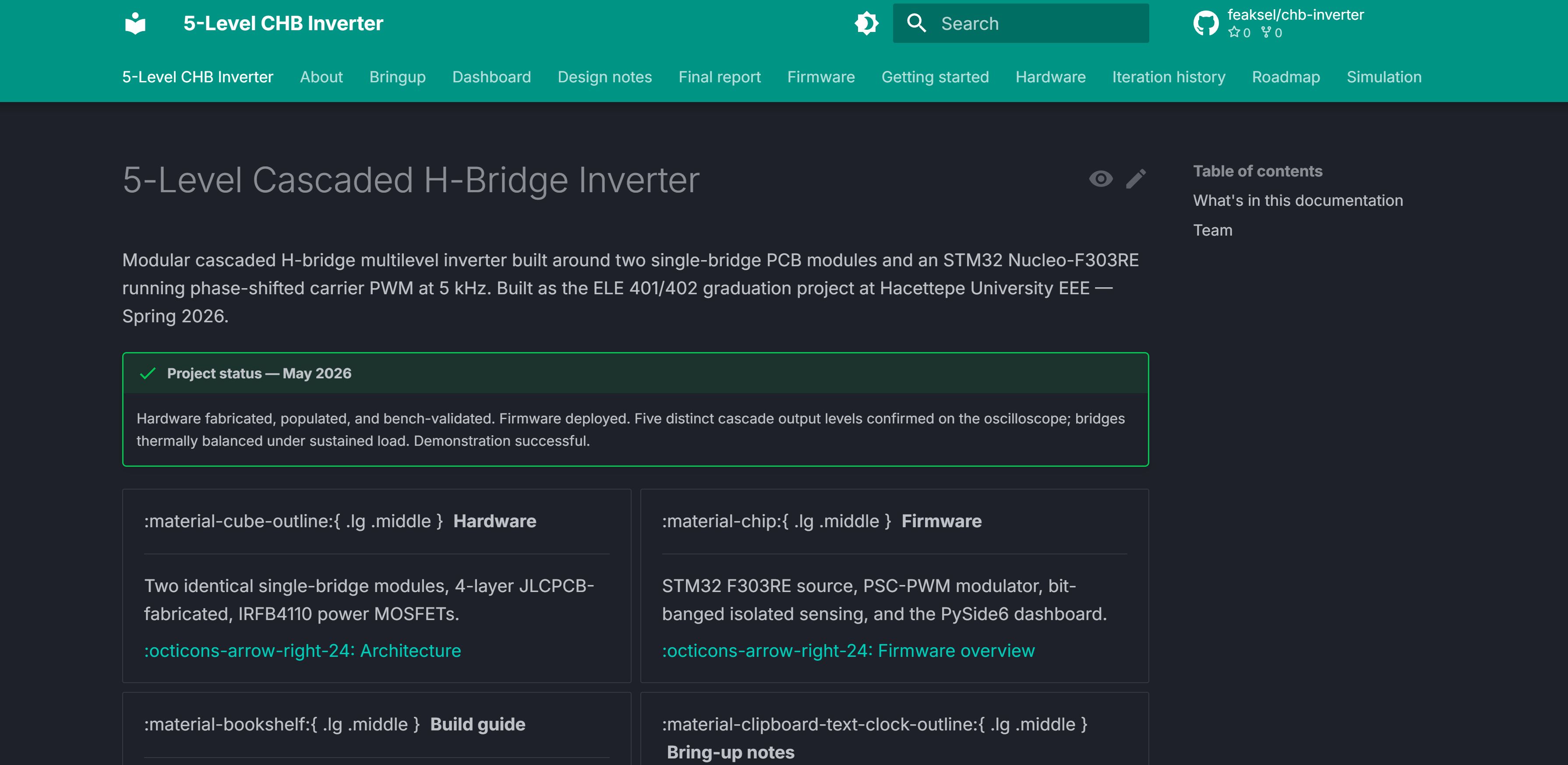
5-Level Cascaded H-Bridge Inverter (ELE 401/402 graduation project, Hacettepe University EEE) — modular CHB topology, STM32 F303RE firmware, PySide6 dashboard. Hardware fabricated and bench-validated.
Chb inverter is an open-source printed circuit board by feaksel, from the feaksel/chb-inverter repository on GitHub, published under the Apache-2.0 licence. It is a 2-layer board of 209.6 × 120.7 mm with 95 parts on 87 nets, routed with 547 tracks and 92 vias.
It is built around the B0515S-1W, MCP3201-CI/P and TLP250(F), with the 6N137#300 and L78L05CZ among its other parts. Its parts include 35 resistors, 26 capacitors, 11 ICs, 10 diodes and 8 connectors. It belongs with the power and interfaces and adapters boards of this library.


One of two identical single-bridge v4 modules — 4-layer JLCPCB, IRFB4110 power MOSFETs in a full H-bridge, TLP250 optical gate drive on a B0515S isolated 15 V rail, bit-banged MCP3201 sensing through 6N137 optocouplers. Cascading two of these externally produces the 5-level output shown below.

The headline result — 100 V output with 5 distinct cascade levels under sustained PSC-PWM at 5 kHz, no filter.



Modular 5-level cascaded H-bridge multilevel inverter built around two single-bridge PCB modules and an STM32 Nucleo-F303RE running phase-shifted carrier PWM at 5 kHz. Bench-validated, demonstrated, and now consolidated into a citable engineering record. Built as the ELE 401/402 graduation project at Hacettepe University EEE — Spring 2026.
Status: Hardware fabricated, populated, and bench-validated. Firmware deployed. Five distinct cascade output levels confirmed on the oscilloscope at 100 V cascade output. Bridges thermally balanced under sustained load. Demonstration successful.
 Documentation site | 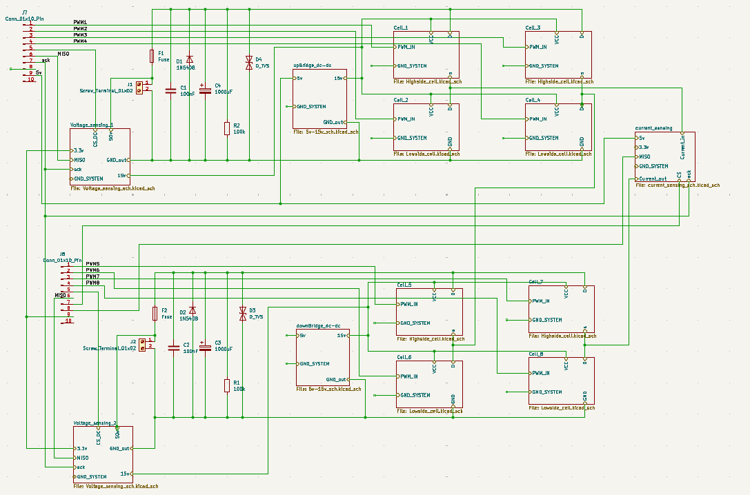 Build Guide v4.0 |  Final report |
 Firmware (STM32 + dashboard) | 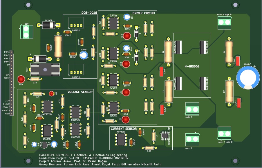 Hardware (KiCad + BOM + gerbers) | 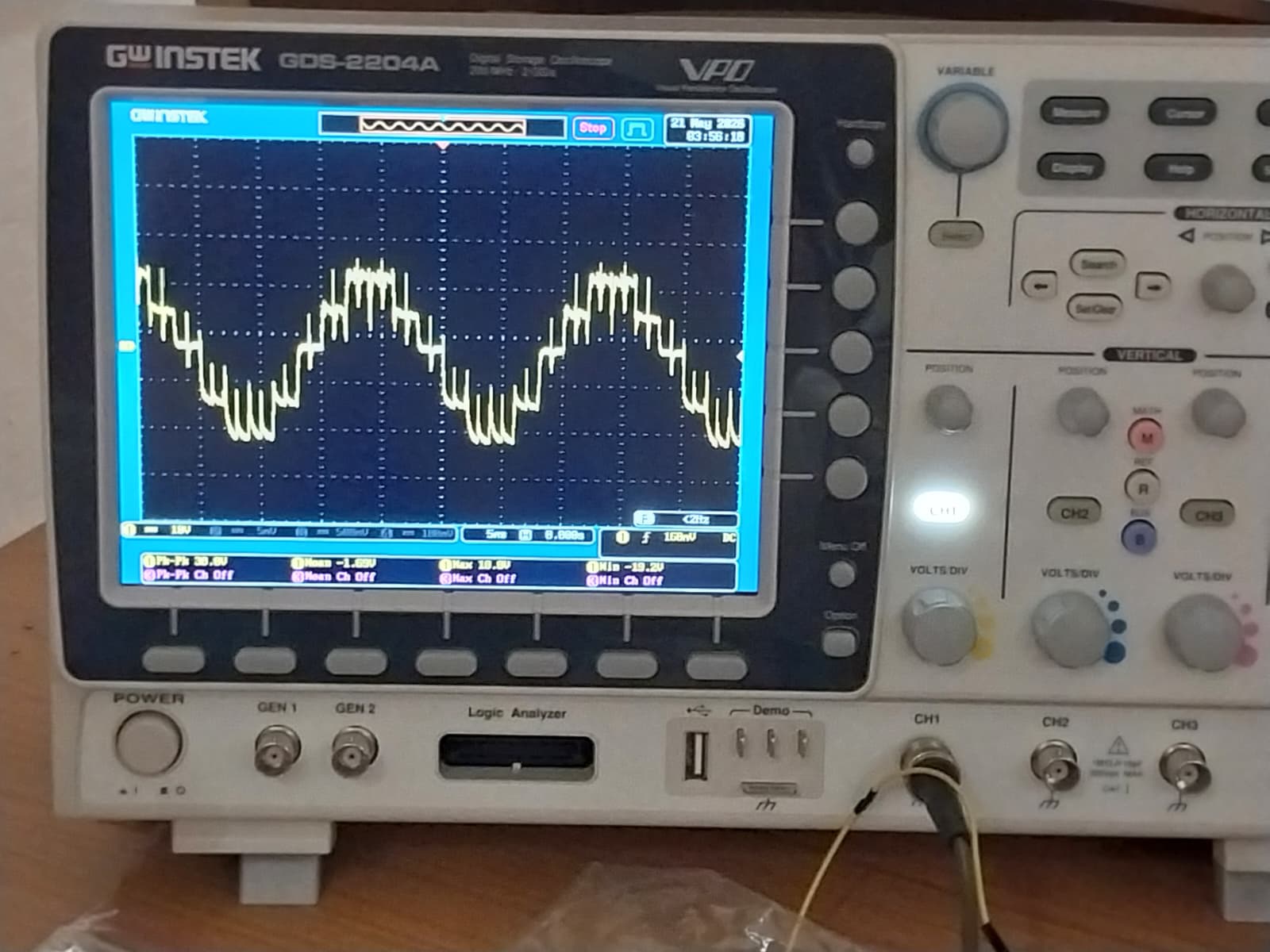 Bring-up session |
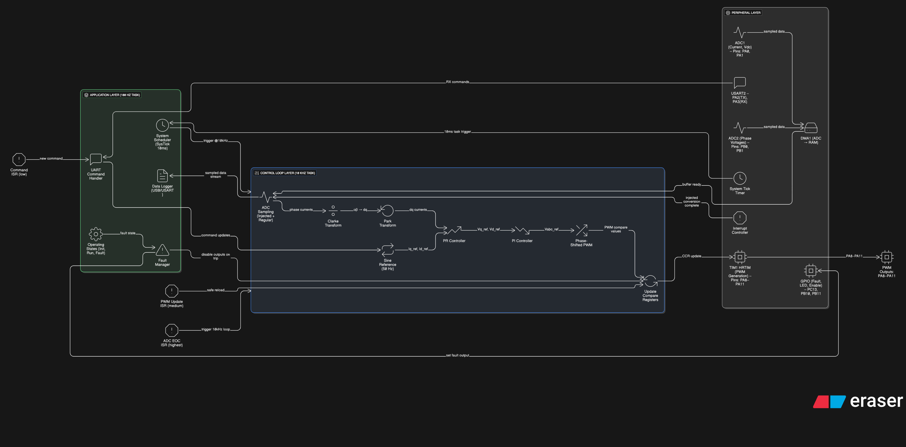
Two identical single-bridge PCB modules (4-layer JLCPCB, IRFB4110 power MOSFETs) cascaded to produce 5 distinct output voltage levels. The STM32 F303RE generates phase-shifted carrier PWM at 5 kHz with bit-banged MCP3201 sensing isolated via 6N137 optocouplers. A PySide6 desktop dashboard provides full operator control over UART.
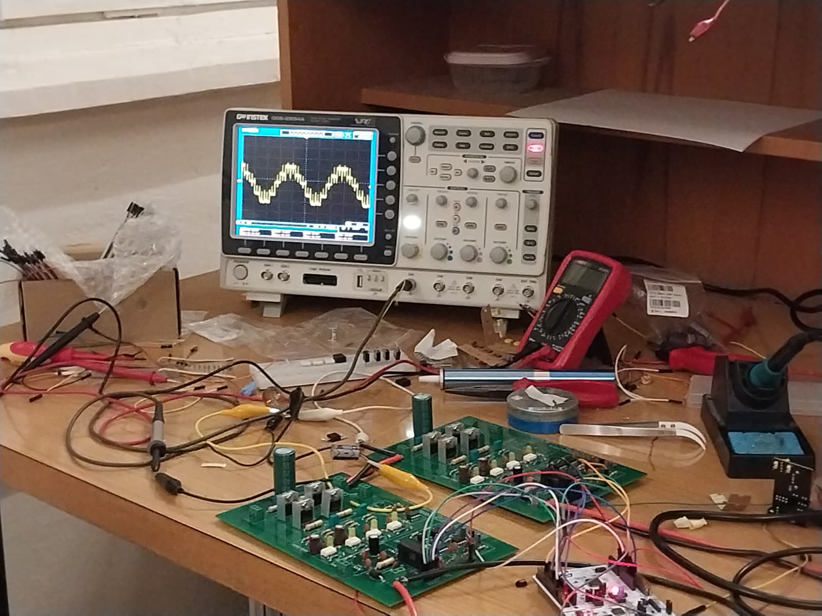
Lab testing setup — the two cascaded single-bridge modules driven by the Nucleo, with the dashboard live on the bench PC.
The PSC modulation gives natural bridge-balance — both H-bridges carry equal switching load. The deviation from the build-guide's original IPD LS-PWM (which had inherent bridge-loss asymmetry) is documented in the PSC vs. LSPWM design note. The iteration story from the early IRFZ44N / IPD layouts through the as-built IRFB4110 / PSC design is in iteration history.
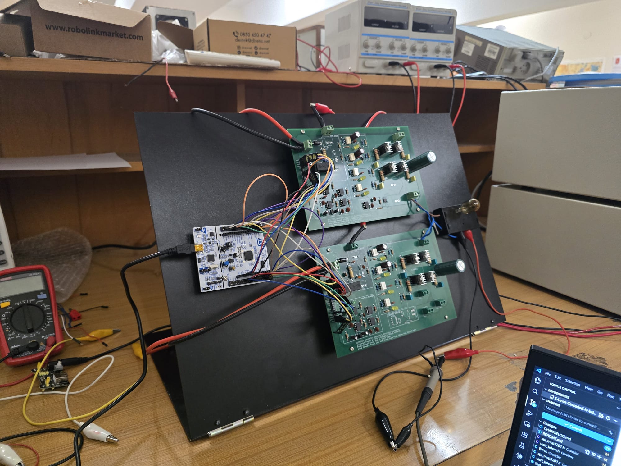
Demo stand — the inverter wired into the bench supplies + load. Five levels visible on the scope as soon as the supplies were brought up.
Project group "Cereyan Hacıları" ("The Current Pilgrims"), under Assoc. Prof. Dr. Rasım Doğan.
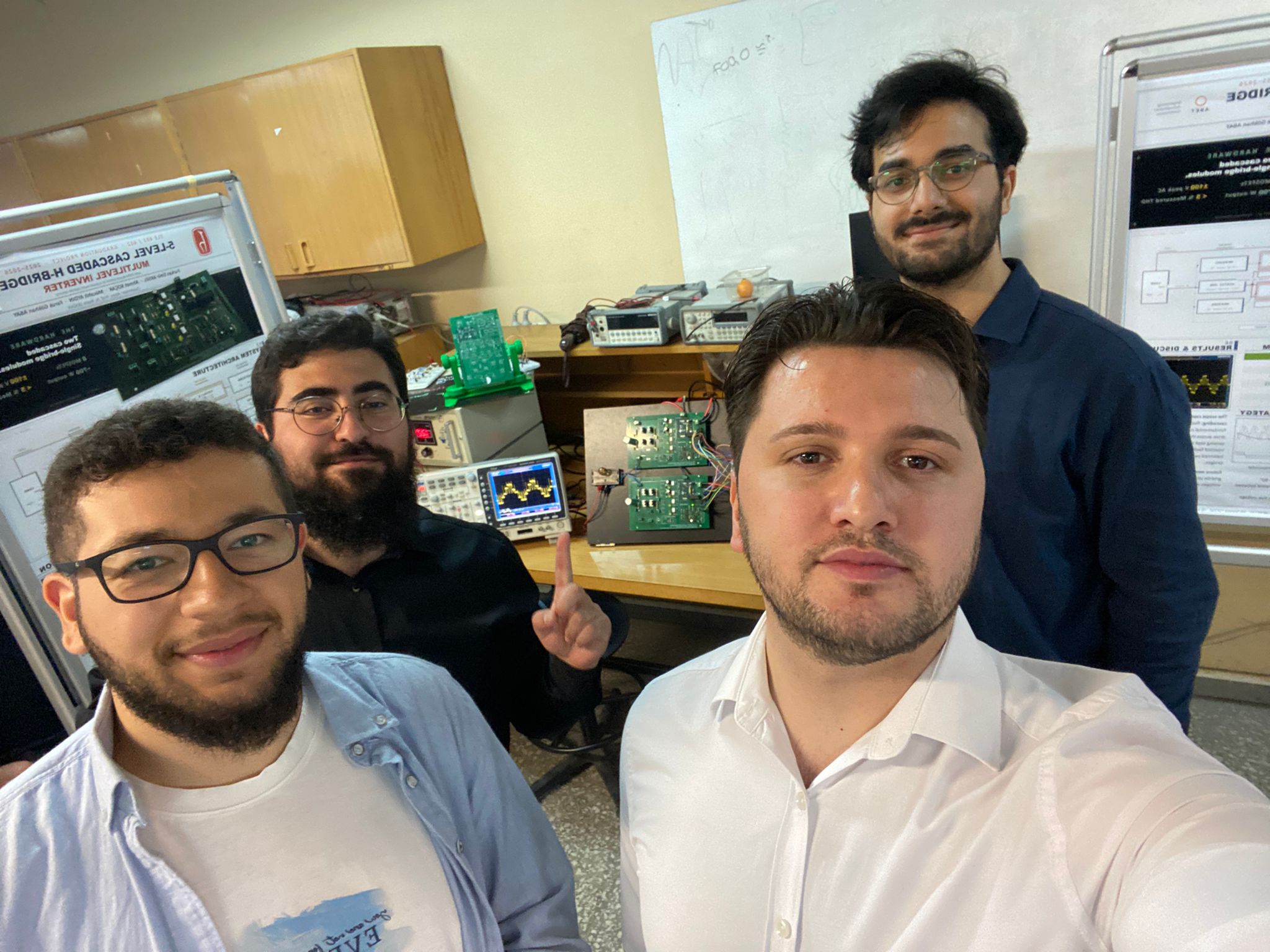
| Furkan Emir Aksel Lead, firmware, dashboard | Ahmet Koçak Hardware, bring-up | Faruk Gökhan Abay Simulation, analysis | Mücahit Aydın Hardware, assembly |

Hacettepe University, Department of Electrical and Electronics Engineering — Ankara, Türkiye, 2026.
chb-inverter/
├── docs/              # MkDocs Material source — every .md becomes a published page
│   ├── hardware/      # Architecture, build guide v4, BOM, schematic, PCB, photos
│   ├── firmware/      # Pin map, state machine, UART protocol, modulators, protection
│   ├── dashboard/     # Operator workflow, install, architecture
│   ├── simulation/    # Simulink THD analysis
│   ├── bringup/       # First-session + reference (rendered from firmware tree)
│   ├── design-notes/  # 5 design-decision deep-dives (bootstrap, isolation, PSC, IGBT, grounding)
│   ├── iteration-history/  # Per-iteration narrative (4 rounds, 1 → 4 as-built)
│   ├── roadmap/       # 6 future-work tracks
│   ├── final-report/  # Consolidated graduation report
│   └── about/         # Team, supervisor, institution, license
├── hardware/          # KiCad project, gerbers, BOM CSV, populated photos
├── firmware/          # STM32 source (git subtree, full history) + PySide6 dashboard
├── simulation/        # Simulink models (3 variants) + analysis
├── experimental/      # RISC-V SoC + FPGA controller — unverified tracks
├── tools/             # BOM validator, link checker, PCB renderer
└── tests/ # Repo-level CI testsApache-2.0. See LICENSE.
If this project informs academic work, please cite it. The full citation metadata is in CITATION.cff.
@software{aksel_2026_chb_inverter,
  author       = {Aksel, Furkan Emir and Koçak, Ahmet and Abay, Faruk Gökhan and Aydın, Mücahit},
  title        = {{5-Level Cascaded H-Bridge Inverter with STM32 Nucleo-F303RE}},
  year         = 2026,
  month        = 5,
  publisher    = {Hacettepe University, Department of Electrical and Electronics Engineering},
  version      = {1.0.0},
  url          = {https://github.com/feaksel/chb-inverter}
}The experimental/ directory contains exploratory tracks that were not validated in silicon and are not part of the graduation deliverable:
experimental/risc-v-soc/ — A custom RV32IM SoC with integrated PWM / ADC / protection / UART / GPIO peripherals, taken through full Cadence Genus → Innovus → GDSII flow against the SkyWater 130 nm PDK. No tape-out; no FPGA equivalence check. Preserved for continuity.experimental/fpga-controller/ — Placeholder for a future FPGA-based controller.For the roadmap of work that would extend the as-built inverter, see docs/roadmap/.
This repository was produced as a graduation project; it is not actively maintained for feature contributions. Issues and pull requests addressing documentation errata, bring-up procedure improvements, or porting to other STM32 variants are welcome. For substantive design changes, please open an issue first to discuss scope.
Built in Ankara, Türkiye · Spring 2026
| Qty | Value | Footprint | References |
|---|---|---|---|
| 16 | 100nF | Capacitor_THT:C_Disc_D5.0mm_W2.5mm_P5.00mm | C1, C5, C8, C10, C13, C25, C26, C27, C33, C35, C38, C39, C40, C43, C48, C49 |
| 7 | 220 | Resistor_THT:R_Axial_DIN0207_L6.3mm_D2.5mm_P10.16mm_Horizontal | R3, R7, R11, R15, R41, R43, R48 |
| 5 | 1k | Resistor_THT:R_Axial_DIN0207_L6.3mm_D2.5mm_P10.16mm_Horizontal | R19, R20, R21, R22, R55 |
| 5 | LED | LED_THT:LED_D5.0mm | D3, D7, D8, D9, D10 |
| 5 | Screw_Terminal_01x02 | TerminalBlock_Phoenix:TerminalBlock_Phoenix_MKDS-1,5-2-5.08_1x02_P5.08mm_Horizontal | J1, J5, J6, J7, J9 |
| 4 | 10K | Resistor_THT:R_Axial_DIN0207_L6.3mm_D2.5mm_P10.16mm_Horizontal | R5, R9, R13, R17 |
| 4 | 2.2nF | Capacitor_THT:C_Rect_L7.2mm_W2.5mm_P5.00mm_FKS2_FKP2_MKS2_MKP2 | C7, C9, C12, C14 |
| 4 | 22 | Resistor_THT:R_Axial_DIN0207_L6.3mm_D2.5mm_P10.16mm_Horizontal | R4, R8, R12, R16 |
| 4 | 22 | Resistor_THT:R_Axial_DIN0617_L17.0mm_D6.0mm_P20.32mm_Horizontal | R6, R10, R14, R18 |
| 4 | Q_NMOS_GDS | Package_TO_SOT_THT:TO-220-3_Vertical | Q1, Q2, Q3, Q4 |
| 4 | TLP250 | Package_DIP:DIP-8_W7.62mm | U1, U2, U3, U4 |
| 3 | 10uF | Capacitor_THT:CP_Radial_D5.0mm_P2.50mm | C6, C11, C45 |
| 3 | 4.7k | Resistor_THT:R_Axial_DIN0207_L6.3mm_D2.5mm_P10.16mm_Horizontal | R42, R44, R50 |
| 2 | 1 | Resistor_THT:R_Axial_DIN0207_L6.3mm_D2.5mm_P10.16mm_Horizontal | R35, R36 |
| 2 | B0515S | my_B0515S:my_B0515S | J3, J4 |
| 2 | D | Diode_THT:D_DO-41_SOD81_P10.16mm_Horizontal | D5, D6 |
| 2 | MCP3201 | Package_DIP:DIP-8_W7.62mm | U10, U20 |
| 1 | 1.5k | Resistor_THT:R_Axial_DIN0207_L6.3mm_D2.5mm_P10.16mm_Horizontal | R56 |
| 1 | 1000uF | Capacitor_THT:CP_Radial_D18.0mm_P7.50mm | C4 |
| 1 | 100k | Resistor_THT:R_Axial_DIN0207_L6.3mm_D2.5mm_P10.16mm_Horizontal | R39 |
| 1 | 100k | Resistor_THT:R_Axial_DIN0617_L17.0mm_D6.0mm_P20.32mm_Horizontal | R2 |
| 1 | 100uF | Capacitor_THT:CP_Radial_D6.3mm_P2.50mm | C28 |
| 1 | 1N5408 | Diode_THT:D_DO-201AD_P15.24mm_Horizontal | D1 |
| 1 | 1uF | Capacitor_THT:CP_Radial_D4.0mm_P1.50mm | C2 |
| 1 | 22k | Resistor_THT:R_Axial_DIN0207_L6.3mm_D2.5mm_P10.16mm_Horizontal | R1 |
| 1 | 330 | Resistor_THT:R_Axial_DIN0207_L6.3mm_D2.5mm_P10.16mm_Horizontal | R23 |
| 1 | 5.1k | Resistor_THT:R_Axial_DIN0207_L6.3mm_D2.5mm_P10.16mm_Horizontal | R40 |
| 1 | 6N137#1 | Package_DIP:DIP-8_W7.62mm | U12 |
| 1 | 6N137#2 | Package_DIP:DIP-8_W7.62mm | U11 |
| 1 | 6N137#3 | Package_DIP:DIP-8_W7.62mm | U13 |
| 1 | ACS712xLCTR-20A | Package_SO:SOIC-8_3.9x4.9mm_P1.27mm | U19 |
| 1 | Conn_01x20_Pin | Connector_PinHeader_2.54mm:PinHeader_1x20_P2.54mm_Vertical | J2 |
| 1 | D_TVS | Diode_THT:D_DO-201AD_P15.24mm_Horizontal | D4 |
| 1 | Fuse | Fuse:Fuseholder_Cylinder-5x20mm_Schurter_0031_8201_Horizontal_Open | F1 |
| 1 | L78L05 | Package_TO_SOT_THT:TO-92_Inline | U9 |
| 1 | LED | LED_THT:LED_D3.0mm | D2 |
RoboDurden/Esp32_20A_80V_dcdc
20A 80V dcdc/mppt with Esp32 and touch display

Wierdwizard2587/ElectricGuitarMK1
This is the repository for the Research and Development, Production, and assembly of the Electric Guitar MK1.

Millisman/EG8010
Collection of designs for the EG8010 (ASIC for single-phase SPWM control H-bridge)

maboytim/TRS-80_Display_Adapter
Display board and CRT replacement for TRS-80 Models 3 and 4 and the big Tandy's.


HNadeemTahir/AI_Inverter_Project
NgSpice Digital Twin of a complete off-grid solar power system: H-Bridge inverter (220V/50Hz, PI control, electro-thermal IGBT modeling) and 4kW MPPT boost converter (UC3843 analog control, KCL summing node, gate drive…

NohPei/GeoMCU
Integrated Geophone Boards with programmable gain and an onboard MCU. Can be used over WiFi or wired with an external ADC.

It measures 209.6 × 120.7 mm and has 2 copper layers, 1.6 mm thick.
95 parts, built around the B0515S-1W, MCP3201-CI/P, TLP250(F) and 6N137#300. The full list of its parts is on this page, with links to each part's symbol and footprint where PCBKit's library has them.
From the feaksel/chb-inverter repository on GitHub, at the commit this page was made from: the board is hardware/single-bridge-v4/kicad/CHB_INVERTER.kicad_pcb and its schematic hardware/single-bridge-v4/kicad/5v-15v_sch.kicad_sch. PCBKit opens the board in the browser, with nothing to install.
Its repository publishes it under the Apache-2.0 licence: you may reuse it on that licence's terms (keep the author's notice, and for a copyleft licence share your changes alike).